Applied Instructions
z l coil and register
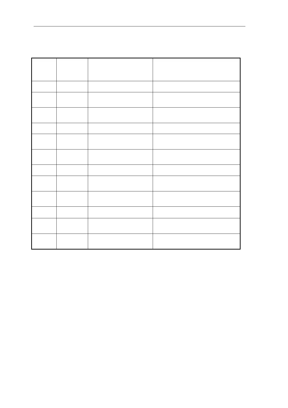
Som flag bits of pulse output is shown below:
ID
High
frequency
pulse ID
Function Description
Pulse output specia
e
M81 0 PULSE_1 Sending pulse flag Be 1 at pulse sending 7
M8171
32 bits pulse sending
Be 1 when overflow
overflow flag
M81 r
ositive direction, the correspond
ire i N
1 is p
72 Di ection flag
d ction port s O
M81 3 PULSE_2 Sending pulse flag Be 1 at pulse sending 7
M81 4
32 bits pulse sending
overflow flag
Be 1 when overflow
7
M8175 Direction flag
1 is positive direction, the correspond
direction port is ON
M81 6 PULSE_3 Sending pulse flag Be 1 at pulse sending 7
M81 7
32 bits pulse sending
overflow flag
Be 1 when overflow
7
M81 8 Di on flag
1 is positive direction, the correspond
direction port is ON
7 recti
M81 9 PULSE_4 Sending pulse flag Be 1 at pulse sending 7
M81 0
32 bits pulse sending
overflow flag
Be 1 when overflow
0
32 bits pulse sending
overflow flag
Be 1 when overflow
8
M8181 Direction flag
is positive direction, the correspond
ec n p t is
1
dir tio or ON
223

 Loading...