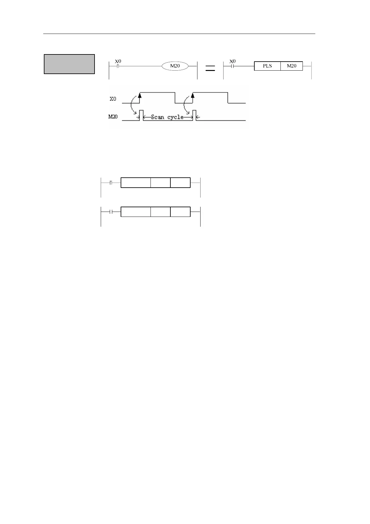
Home
Thinget
Controller
XC Series
Thinget XC Series User Manual
4
of 1
of 1 rating
283 pages
Give review
Manual
Specs
To Next Page
To Next Page
To Previous Page
To Previous Page
Loading...
Basic SFC Functions
In two c
onditions, when X0 tur
ns from OFF to ON, M20 gets
a scan cycle.
NOTE:
X10
MOV
K10
D0
X10
MOV
K10
D0
Output drive
When X10 turns from OFF to ON,
only execut
e once MOV instruction.
When X10 turns from OFF to ON,
each scan cycle execute once
MOV
instruction.
54
53
55
Table of Contents
Table of Contents
2
Product Characteristics
4
Overview
5
Summary of XC Series PLC and Program Format
6
XC Series Programmable Controller
6
Statement Program
6
Ladder Program
6
XC Series Plc’s Model and Type
7
Summary of XC Series PLC
8
Digital I/O Expansions
9
Expansion’s Constitution and ID Assignment
10
Constitution Rules
10
ID Assignment
11
General Specification
12
Performance
13
Shape and Size
14
Exterior Size
14
Terminal Arrangement
16
Expansions
18
COM Port Definition
19
Power Specification
21
AC Power Type
21
DC Power Type
21
AC Power, DC Input Type
22
Constitution and Connection
22
Spec., Input/Output and Layout
22
Input Specification
23
DC Input Signal’s Disposal (AC Power Type)
24
Exterior Circuit Used
25
Input Connection
25
Output Specification
26
Disposal of Relay Output Circuit
27
Disposal of Transistor Output Circuit
29
Each Soft Unit’s Usage and Function
31
Every Soft Unit of Programmable Controller
32
Function of each Device
32
Device’s ID List
34
Setting of Soft Unit’s Power Failure Saving Area
35
Data Disposal of Programmable Controller
36
Some Encode Principles of Device
37
Timer’s Number and Function
39
Assign Method of the Set Value
40
The Time Value
40
Action
40
Counter’s ID and Function
41
16 Bits Counter
42
32 Bits Counter
43
Action Order of Input/Output Relay and Response Delay
45
Not Accept Narrow Input Pulse Signal
45
Basic Program Instructions
46
List of Basic Instructions
47
Basic SFC Instructions
47
LD, LDI, out
49
And, ANI
50
Or, Ori
51
Ldp, Ldf, Andp, Andf, Orp, Orf
52
Relationship with ANB
52
Orb
55
Anb
56
Mcs, Mcr
57
Alt
58
Pls, Plf
59
Set, Rst
60
OUT, RST for the Counters
61
Nop, End
62
Dual Output Dual Coil’s Activation and the Solution
63
Contacts’ Structure and Step Number
63
Program’s Executing Sequence
63
Items to Note When Programming
63
Applied Instructions
64
Common Statements of XC3/XC5
67
Reading Method of Applied Instructions
68
Instructions List of 16 Bits and Correspond 32 Bits
70
Program Flow Instructions
71
Condition Jump [CJ]
72
Call Subroutine (Call) and Subroutine Return (SRET)
73
Flow [SET], [ST], [STL], [STLE]
74
(FOR) and (NEXT)
75
(Fend) and (End)
76
Contactor’s Compare Instructions
77
Mnemonic & Function
77
Initial Comparison LD
78
Serial Refer below and
79
Parallel Comparision or
81
Data Move
82
Mov
83
Bmov
84
Fmov
85
Fwrt
86
Mset
87
Swap
88
Xch
89
Data Operation Instructions
90
Addition Operation [ADD]
91
Sub
92
Mul
93
DIV
94
[Inc] & [Dec]
95
Mean
96
[Wand], [WOR], [WXOR]
97
[Cml]
98
[Neg]
99
Shift Instructions
100
[Shl] & [Shr]
101
[Lsl] & [Lsr]
102
[Rol] & [Ror]
103
[Sftl] & [Sftr]
104
[Wsfl] & [Wsfr]
105
Data Convert
106
[Wtd]
107
[Flt] & [Fltd]
108
[Int]
109
[Bin]
110
[Bcd]
111
[Asci]
112
[Hex]
113
[Deco]
114
[Enco]
115
[Encol]
116
Floating Operation
117
[Ecmp]
118
[Ezcp]
119
[Eadd]
120
[Esub]
121
[Emul]
122
[Ediv]
123
[Esqr]
124
Clock Operation
128
Time Compare [TCMP]
129
[Tzcp]
130
[Tadd]
131
[Tsub]
132
[Trd]
133
[Twr]
134
Applied Instruction List
136
Common Statements
138
Call Subroutine [CALL] and Subroutine Return [SRET]
144
[FOR] and [NEXT]
146
Special Function Instructions
206
High-Speed Count Function
207
The Assignment of Count Input Ports
207
Definition of High Speed Counter’s Input Terminals
208
Input Mode of High Speed Counter’s Signal
209
Connection of Input Terminal
211
Times Frequency
213
Pulse Output Function
214
Type and Application of Pulse Output
214
Pulse Output of Single Segment and Single Direction
216
Pulse Output of Segments and Single Phase
217
Dual Pulse Output with Speedup/Speed-Down
218
Connection of Output Terminals
220
Note Items
221
Pulse Output Special Coil and Register
223
Communication Function
225
COM Port
225
Communication Parameter
227
Parameter Setting
228
MODBUS Communication Function
230
Communication Instructions
231
Free Format Communication
235
Instruction Format
236
PWM Pulse Width Modulation
237
Frequency Testing
238
Precise Time
239
Interruption Function
242
External Interrupt
242
Time Interrupt
245
Limitation of Interruption’s Bound
246
Disable Interruption
246
CAN-Bus Function (XC5 Series)
247
Coil Write Statement
248
Coil Read Statement
248
Network Format of CAN Bus
248
Write Register Statement
249
Read Register Statement
249
Interior Protocol Communication Form
250
CAN Communication Setting
251
CAN Baud Rate Setting Table
252
CAN Node Status
252
CAN Status Flag
253
CAN Status Register
253
Applied Example Programs
254
Example of Pulse Output
255
Example of MODBUS Instructions
257
Compile Communication Program
258
Example of Free Format Communication
258
Format of Communication Instructions
258
Interface Specification
258
Appendix
263
List of Special Auxiliary Relay, Special Data Register
264
PC Status
264
Clock (M)
265
Flag (M)
265
Clock (D)
266
Flag (D)
266
PC Mode
267
Step Ladder (M)
268
Interrupt (M)
268
Error Check
269
Communication (M)
270
Communication (D)
271
High Speed Count
272
Pulse Output
273
High Speed Count (D)
274
Pulse Output (D)
275
Expansion’s Information (D)
276
List of Special FLASH Data Register SFD
277
Brief Introduction of XC1 Series PLC
279
Soft Unit’s Bound
281
XC5 Series PLC
282
4
Based on 1 rating
Ask a question
Give review
Questions and Answers:
Need help?
Do you have a question about the Thinget XC Series and is the answer not in the manual?
Ask a question
Thinget XC Series Specifications
General
Brand
Thinget
Model
XC Series
Category
Controller
Language
English
Related product manuals
Thinget XC3-24T-E
283 pages
Thinget XC3-60T-E
283 pages
Thinget XC3-24RT-E
283 pages