5
5-9
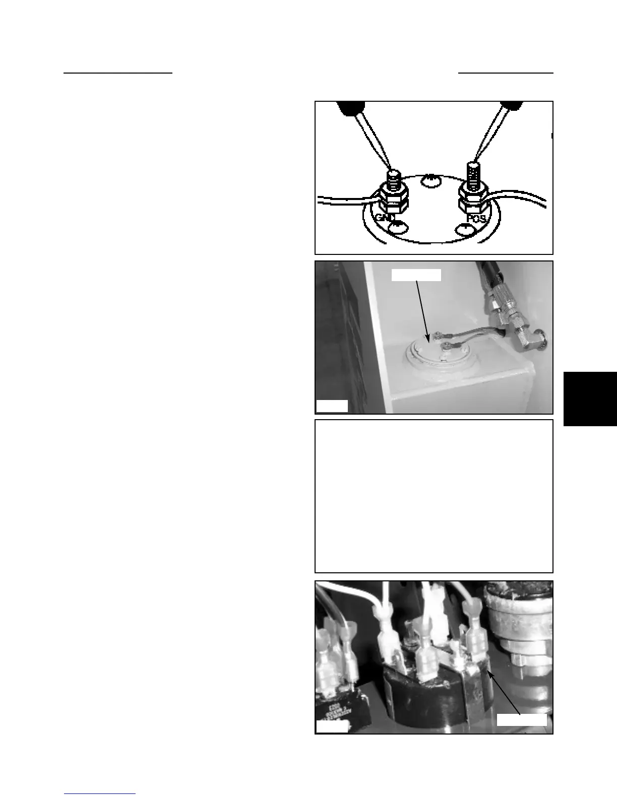
1 With the ignition switch off, connect an ohmmeter
between the positive and negative terminals of the fuel
sending unit. (fig. C306)
2 An ohmmeter reading of 50 to 500 is normal. A read-
ing higher or lower means a faulty sender and will need
replaced.
Testing the Fuel Sender
Replacement
1 Remove any attachment, raise the boom arms and
engage the boom support pins. Shut off the engine and
engage the parking brake.
2 Remove the 2 wires connected to the fuel sending
unit. The fuel sender is located just below the lift cylin-
der, right hand side, on the fuel tank. (fig. C5089)
3 Remove the 5 screws retaining the sender to the fuel
tank.
4 Remove the sending unit and discard the gasket.
5 Install a new sending unit and gasket. Use gasket
sealant on both sides of the gasket.
6 Use thread sealant on the screws and torque the
screws to 20 inch lbs.
7 Connect the sender wires taking care not to over
tighten the nuts and stripping the studs. Green wire is
ground.
Testing the Fuel
Sender/Hour Meter
LB002500 Onward
The hour meter records the number of engine operating
hours.
LB002500 Onward
1 To check the fuel sender, remove the dash panel.
2 Withe the ignition switch off, connect an ohmmeter
between the #1 and the #3 terminals.
3 An ohmmeter reading of 150 to 200ohms is normal.
A higher or lower reading means the gauge is faulty and
needs to be replaced.
NOTE: If the fuel gauge test results were good and the
gauge still fails to function, do the following test.
1 With the ignition switch off, connect an ohmmeter
between the #1 terminal and the other end to ground.
2 An ohmmeter reading of 50 to 500 ohms is normal.
A higher or lower reading means the wire going to the #1
terminal is faulty.
NOTE: If test is good, check the fuel level sender.
INSTRUMENTATION 5.3
C5089
C5091
C5090
Sender unit
C306
Hour meter