5
5-18
SAFETY CIRCUIT 5.10
General Information
The loader is equipped with 3 inter - connected safety
switches. These switches operate 2 electric solenoid con-
trolled lock devices and a starter interlock system. One
(1) pair of solenoid coils on the hydraulic control valve .
The operation of the solenoid coils and loader functions
will be prevented if one of these safety switches are
open. For proper operation of the solenoid coils and
loader functions, all 3 must be hooked up, functioning
and, if applicable, adjusted correctly. There is also a
switch that controls the dash panel brake warning light.
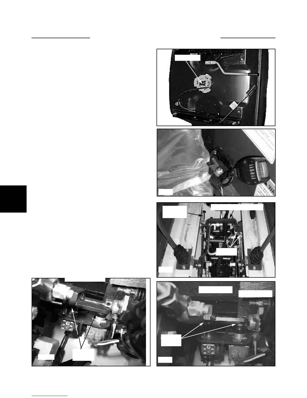
The bottom of the operators seat is equipped with a pres-
sure sensitive switch.(fig. C807) The operator must be in
the seat to close the switch and release the parking brake
and unlock the control valve functions. No adjustments
required. When removing and replacing the seat, be sure
not to pinch the wires under the seat plate.
The seat belt assembly is equipped with a safety switch.
The operator must have the seat belt fastened around
them in order to close the switch and allow the parking
brake to release and the control valve to function. (fig.
C5020) No adjustments required.
The restraint bar controls two safety switches (fig.
C5628) located under the operators seat assembly. With
the restraint bar in the raised position, the parking brake
is activated, the control valve functions are locked and the
activation indicator lights are illuminated on the dash
panel. (fig C5629)
Lowering the restraint bar releases the parking brake,
turns off the indicator lights in the dash panel and releas-
es the locks in the control valve. (fig. C5630)
The restraint bar must be in the lowered position for the
control functions to operate.
C5020
C807
Seat switch
C5629
C5628
Brake pull off assembly
Restraint
bar cable
Safety switches
C5630
Restraint bar up
Switches
open
Restraint bar down
Switches
closed
Switches