5-19
5
Switch Adjustment
SAFETY CIRCUIT 5.10
1 Remove any attachment, raise the boom arms and
engage the boom support pins. Shut off the engine.
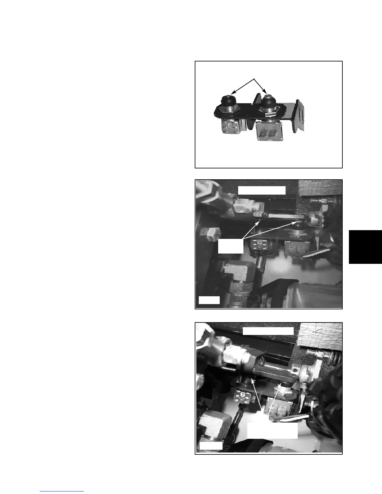
2 Remove the seat. Visually check to ensure that both
switches have the same gap to the brake arm shaft
tab.(fig, C5629)If they are not the same, adjust the gaps
so that they are even using the switch mounting nuts.
3 Locate the switch mount bracket under the left side of
the brake pull off assembly. Loosen the two mounting
bolts that hold the switch bracket.
4 Lower the restraint bar.
5 Lift up on the switch assembly until the the switches
are fully depressed, then lower the assembly 1/8” (3mm).
This ensures that the switches do not bottom out and
break during normal operation. Tighten the mounting
bolts until snug. (fig. C5630)
6 Carefully cycle the restraint bar up and down while
observing switch function. Check for a gap between
switches and brake shaft tab when the resrtraint bar is
fully raised.
C5630
C5629
Restraint Bar up
Gap over
switches
Restraint Bar down
Switches not fully
depressed
1 Remove the seat. Raise the restraint bar.
2 Remove wires from the switch to be replaced.
3 Remove the rubber boot from the switch.
4 Remove the upper nut, and drop the switch out of the
bracket mount.
5 Prepare the new switch for installation by removing
boot and the top nut. Adjust the lower nut to the same
height as the lower nut on the old switch.
6 Insert the switch into the bracket mount and start the
top nut onto the switch. Tighten the top nut and check
that the new switch is set at the same height as the other
switch..(fig. C5636)
7 Slowly cycle the restraint bar down and up to check
that the switch is not bottoming out. Readjust if neces-
sary to obtain proper operation of the switch.
8 Install the rubber boot and connect the wires to the
switch.
Switch Replacement
C5636
Set height equal