5-21
5
ELECTRIC AUXILIARY CIRCUIT 5.11
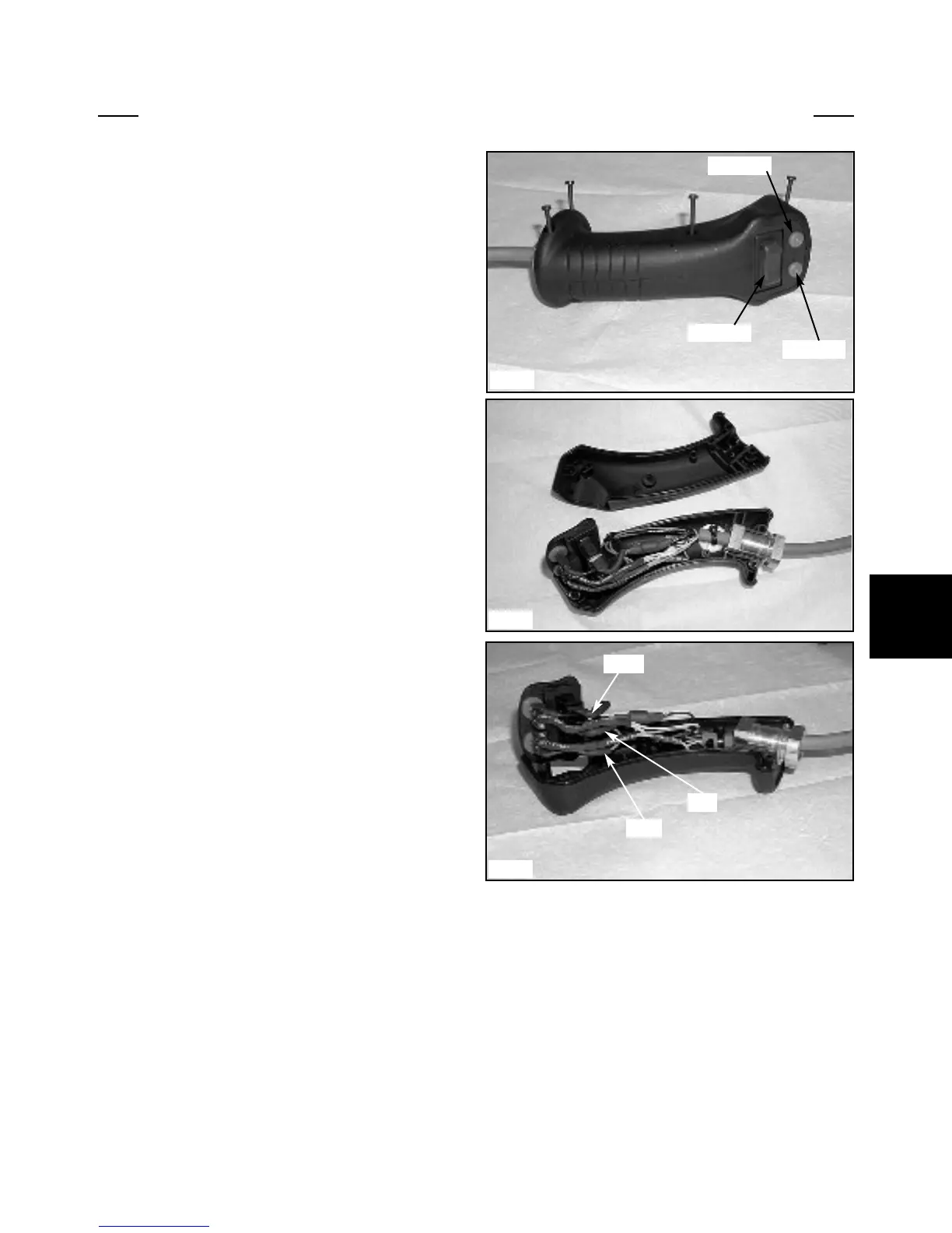
THE ERGONOMIC HANDLE CONTROL:
The Ergonomic Handle contains 3 switches: 1 rocker
switch and 2 push button switches. (fig. 2945)
The handle is normally installed only on the left hand
control lever for the 85 loader.
When installed on the LH lever:
1. The rocker switch controls the electric aux. func-
tions. Pushing down on the left side of the rocker switch
is the forward direction and pushing down on the right
side is the reverse direction.
2. The LH push button is a spare to be used if adding
an option.
3. The RH push button is for the horn.
When installed on the RH lever:
1. The rocker switch is used to control the Hi-Flow
option. Pushing down on the left side of the rocker switch
is the forward direction and pushing down on the right
side of the rocker switch is the reverse direction.
2. The LH and RH buttons are used to turn the signal
lights on when the light kit option is installed.
To replace a defective switch:
1. Ensure the ignition switch is in the OFF position.
2. Remove the 4 screws that hold the 2 handle pieces
together. (fig. C2946)
3. Remove the LH handle piece and pull the
switch/wire assembly out of the RH handle piece.
4. The original rocker switch has the wires soldered
to the terminals of the switch. Take note of the wire color
attached to each terminal before removing the wires.
5. The rocker switch has a tab on each end of the
switch which needs to be depressed before removing the
switch.
6. The rubber rocker cover can be replaced or reused
on the replacement rocker switch at this time.
7. Replace the switch and reattach the wires. Proper
female spade terminals may be soldered to the wires.
After servicing the control handle be sure the hydraulic
flow is circulating in the proper direction. Pushing on the
LH side of the switch should engage the hydraulic system
in the forward direction. The female quick coupling must
always be the power out when engaging the control
mounted switch in this direction.
5-21
C2945
C2947
C2946
Button A
Button B
Switch C
Black
Blue
Red