0 1
-
S C E N E 1
Normal use state
1
INPUT SELECT
I N 1
-
I N 1 : O F F
I N 1
-
-
-
-
-
-
-
I N 1
-
I N 1 : O N 0. 0
I-ON/OFF
P
or
IN
: +10 to -70, ∞ (0.5 dB steps)
To/from lowermost screen
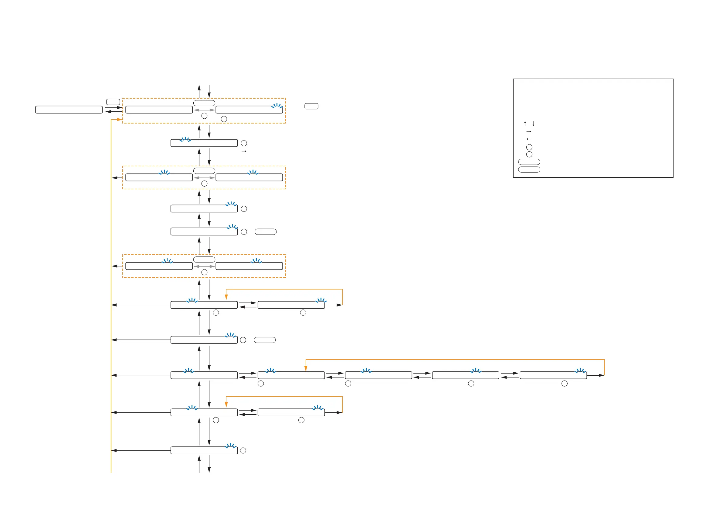
The screen display examples may differ from actual displays.
The on-screen indications shown in blue are variable parameters
by key operation.
The symbols in the figure represent the following key operation.
: Screen shift keys (up and down)
: Screen shift key (right) or ENTER key
: Screen shift key (left) or ESC key
: PARAMETER knob
: INPUT VOLUME knob
: Input channel ON/OFF key
: Output channel ON/OFF key
I-ON/OFF
O-ON/OFF
P
IN
(p.56-A1)
P A G I N G O F F P A G I N G O N
I-ON/OFF
P
or
(p.56-A3)
I N 1
-
N O M
-
O FF I N 1
-
N O M
-
O N
I-ON/OFF
P
or
(p.57-A6)
(p.56-A2)
1
INPUT SELECT
: Cycles meter display (FADER /LEVEL) below
the setting screen each time pressed.
: Selects characters to enter.
(Right shift key): Moves the cursor to the right.
P
I N 1
-
S E N S I T I V I T Y
-
1 0
(p.56-A4)
:
-
10,
-
18,
-
24,
-
36,
-
42,
-
48,
-
54,
-
60 (dB)
P
I N 1
-
P H A N T O M O F F
(p.57-A5)
or : ON/OFF
P
I-ON/OFF
L O U D N E S S
-
O F F
(p.57-A8)
or : ON/OFF
P
I-ON/OFF
C O M P R E S S O R
-
O F F
(p.58-A11)
: OFF, 1, 2, 3, 4, 5
P
B A S S 0 T R E B L E 0
(p.57-A7)
: +12 to
-
12
(1 dB steps)
P
B A S S 0 T R E B L E 0
(p.57-A7)
: +12 to
-
12
(1 dB steps)
P
Only when Paging is set to OFF
H P F
-
O F F L P F
-
O F F
(p.58-A10)
: OFF,
20Hz to 20kHz,
31 points
P
: 20 (Hz) to 20 (kHz),
OFF,
31 points
P
H P F
-
O F F L P F
-
O F F
(p.58-A10)
E Q
-
O F F
(p.58-A9)
E Q 0 1 0 d B Q 1. 5 3 1. 5
(p.58-A9)
: 1 to 10
P
E Q 0 1 0 d B Q 1. 5 3 1. 5
(p.58-A9)
: +12 to
-
12 (1 dB steps)
P
E Q 0 1 0 d B Q 1. 5 3 1. 5
(p.58-A9)
: 0.3 to 5
P
E Q 0 1 0 d B Q 1. 5 3 1. 5
(p.58-A9)
: 20 to 20 (kHz)
P
When set to OFF, setting menu at
right is not displayed.
To the next page
Goes to the next band setting.
10.2.1. Input setting flow chart for the channel on which the D-001T or D-001R is used
10.2. Input Setting Flow Chart
Setting items differ depending on the modules used for input channels.
Refer to this page when the D-001T or D-001R is used, p. 54 when the ZP-001T is used, and p. 55 when the AN-001T is used.