0 1
-
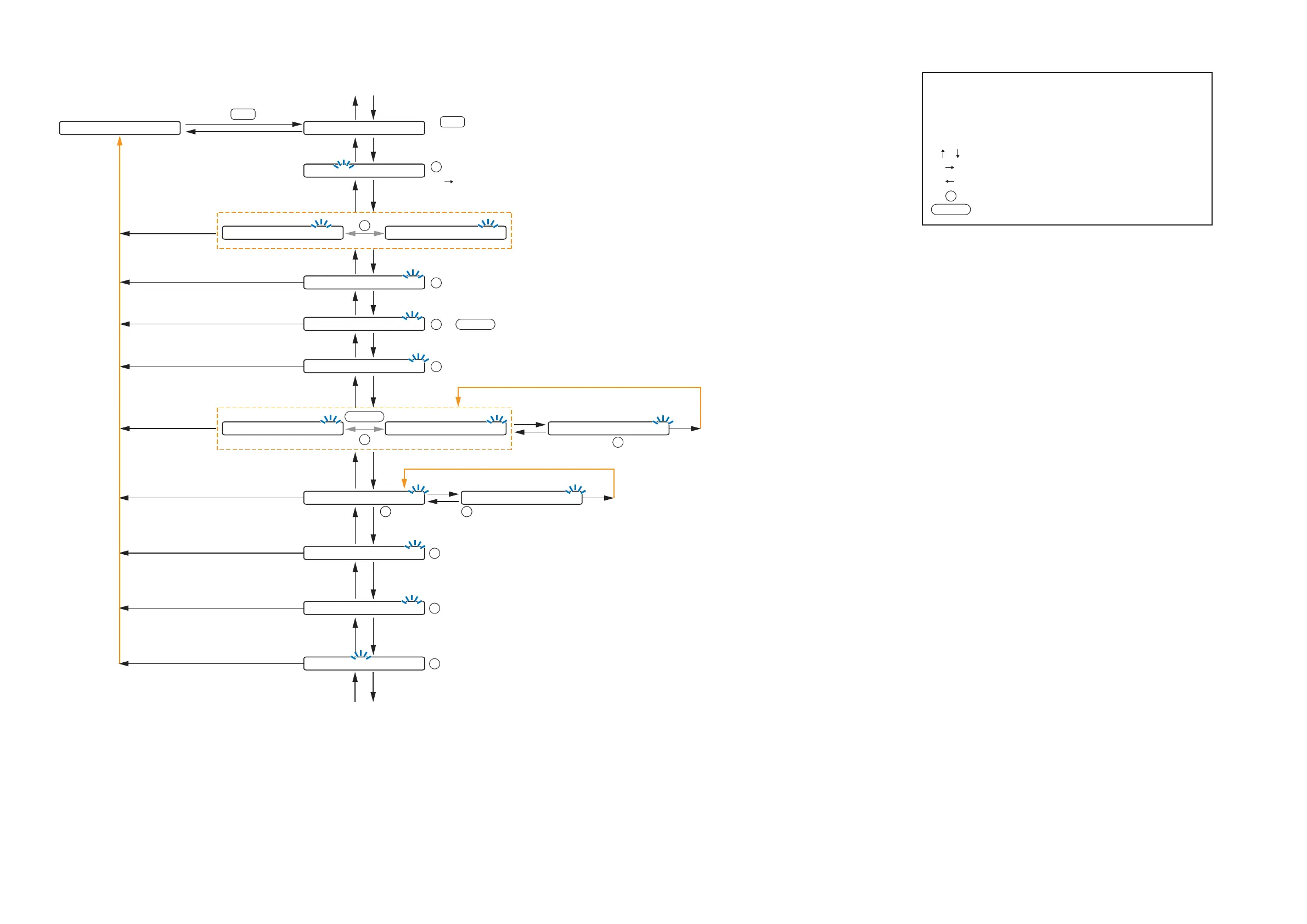
S C E N E 1
Normal use state
1
INPUT SELECT
A N C 1
-
I N 3
A N C 1
-
-
-
-
-
-
-
-
To/from lowermost screen
The screen display examples may differ from actual displays.
The on-screen indications shown in blue are variable parameters
by key operation.
The symbols in the figure represent the following key operation.
: Screen shift keys (up and down)
: Screen shift key (right) or ENTER key
: Screen shift key (left) or ESC key
: PARAMETER knob
: Input channel ON/OFF key
I-ON/OFF
P
A N C 1
-
B Y P A S S A N C 1
-
ACTIVE
P
(p.64-A35)
M O N I T O R O U T
-
O F F M O N I T O R O U T
-
O N
I-ON/OFF
P
or
(p.65-A39)
(p.64-A34)
1
INPUT SELECT
: Cycles meter display (FADER /LEVEL) below the setting screen each time pressed.
: Selects characters to enter.
(Right shift key): Moves the cursor to the right.
P
A N C
-
S E N S I T I V I T Y
-
1 0
(p.64-A36)
:
-
10,
-
18,
-
24,
-
36,
-
42,
-
48,
-
54,
-
60 (dB)
P
A N C
-
P H A N T O M O F F
(p.64-A37)
or : ON/OFF
P
I-ON/OFF
S A M P L E T I M E 2 0
(p.65-A43)
: 10, 15, 20, 30, 60, 120, 180, 300 (sec)
P
M A X I M U M L E V E L 0
(p.65-A41)
: 0,
-
3 (dB)
P
M I N I M U M L E V E L
-
6
(p.65-A42)
:
-
3,
-
6,
-
9,
-
12,
-
15,
-
18 (dB)
P
A N C
-
A P P L I E S
-
> O U T 1
(p.64-A38)
: 1, 2, 3, 4
P
M O N I T O R O U T
-
O U T 4
(p.65-A40)
: 1, 2, 3, 4
P
G A I N , R A T I O 3 : 3
(p.66-A44)
: 6:5, 5:3, 4:3, 3:3, 3:4, 3:5, 3:6, 6:
-
3, 5:
-
3, 4:
-
3,
3:
-
3, 6:
-
3, 5:
-
3, 4:
-
3, 3:
-
3, 3:
-
4, 3:
-
5, 3:
-
6
P
A N C A D J 0 S E N S
-
5 0
(p.66-A45)
:
-
10 to +10 (1 dB steps)
P
To/from uppermost screen
10.2.3. Setting flow chart for the channel on which the AN-001T is used