67
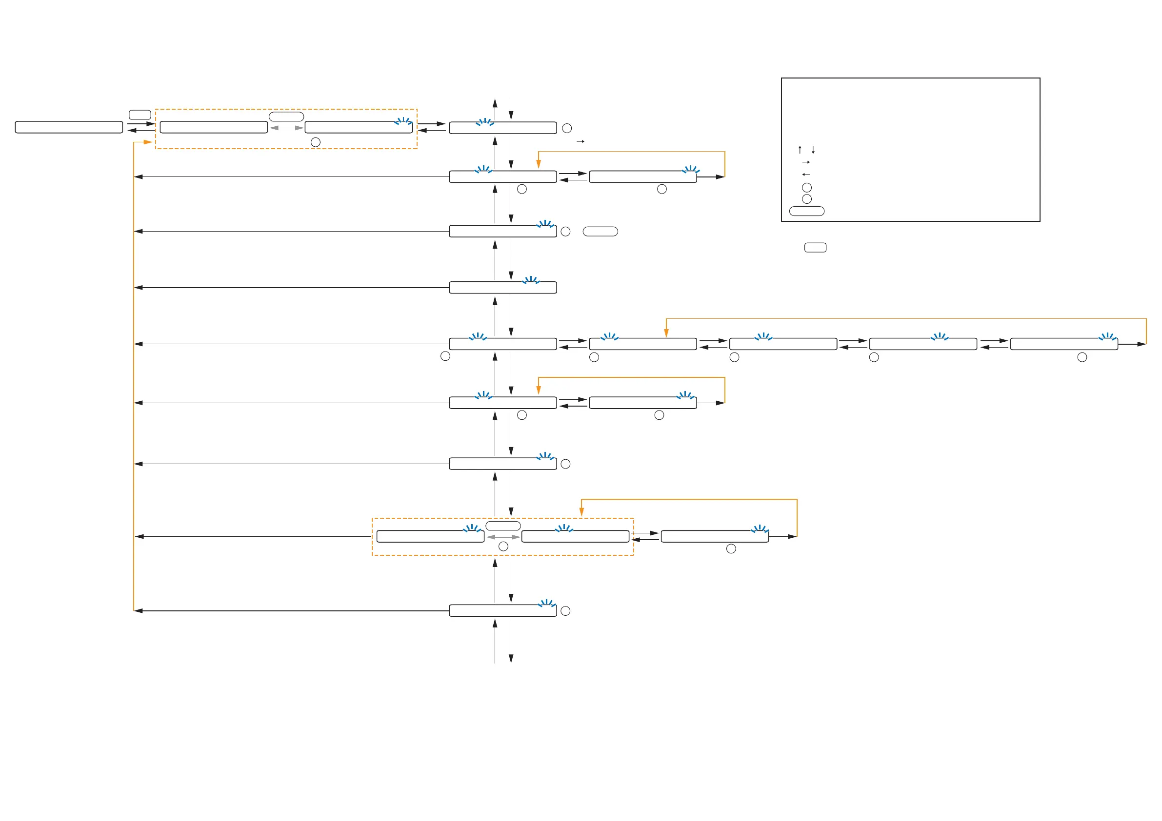
10.3. Output Setting Flow Chart
0 1
-
S C E N E 1
Normal use state
OUTPUT SEL
OUT 1
-
O U T 1 : O F F
O U T 1
-
-
-
-
-
-
-
-
OUT 1
-
O U T 1 : O N
-
2 0. 0
O-ON/OFF
OU
: +10 to
-
70,
-
∞ (0.5 dB steps)
To/from lowermost screen
The screen display examples may differ from actual displays.
The on-screen indications shown in blue are variable parameters
by key operation.
The symbols in the figure represent the following key operation.
: Screen shift keys (up and down)
: Screen shift key (right) or ENTER key
: Screen shift key (left) or ESC key
: PARAMETER knob
: OUTPUT VOLUME knob
: Output channel ON/OFF key
O-ON/OFF
P
OU
(p.68-B1)
D E L A Y
-
O FF D E L A Y
-
O N T I M E 0. 0
O-ON/OFF
P
or
(p.71-B9)
(p.68-B2)
OUTPUT SEL
: Cycles meter display (FADER/LEVEL) below
the setting screen each time pressed.
: Selects characters to enter.
[ ] (Right shift key): Moves the cursor to the right.
P
L O U D N E S S
-
O F F
(p.68-B4)
or : ON/OFF
P
O-ON/OFF
: ON/OFF
P
C O M P R E S S O R
-
O F F
(p.71-B8)
: OFF, 1, 2, 3, 4, 5
P
B A S S 0 T R E B L E 0
(p.68-B3)
: +12 to
-
12
(1 dB steps)
P
B A S S 0 T R E B L E 0
(p.68-B3)
: +12 to
-
12
(1 dB steps)
P
H P F
-
O F F L P F
-
O F F
(p.70-B7)
: OFF,
20Hz to 20kHz,
31 points
P
: 20 (Hz) to 20 (kHz),
OFF,
31 points
P
H P F
-
O F F L P F
-
O F F
(p.70-B7)
E Q
-
O F F
(p.70-B6)
E Q 0 1 0 d B Q 1. 5 3 1. 5
(p.70-B6)
: 1 to 10
P
E Q 0 1 0 d B Q 1. 5 3 1. 5
(p.70-B6)
: +12 to
-
12 (1 dB steps)
P
E Q 0 1 0 d B Q 1. 5 3 1. 5
(p.70-B6)
: 0.3, 0.5, 0.7, 1, 1.5, 2, 3.5
(7 points)
P
E Q 0 1 0 d B Q 1. 5 3 1. 5
(p.70-B6)
: 20 to 20k
(31 points)
P
Goes to the next band setting.
: 0 to 40
(1 msec steps)
P
D E L A Y
-
O N T I M E 0. 0
(p.72-B10)
P A G I N G
-
O U T V R :
-
2 0
(p.72-B11)
: 0 to
-
70 (dB),
-
∞
(1 dB steps)
S P E Q
-
> A L L F L A T
(p.69-B5)
To/from uppermost screen
OU