91
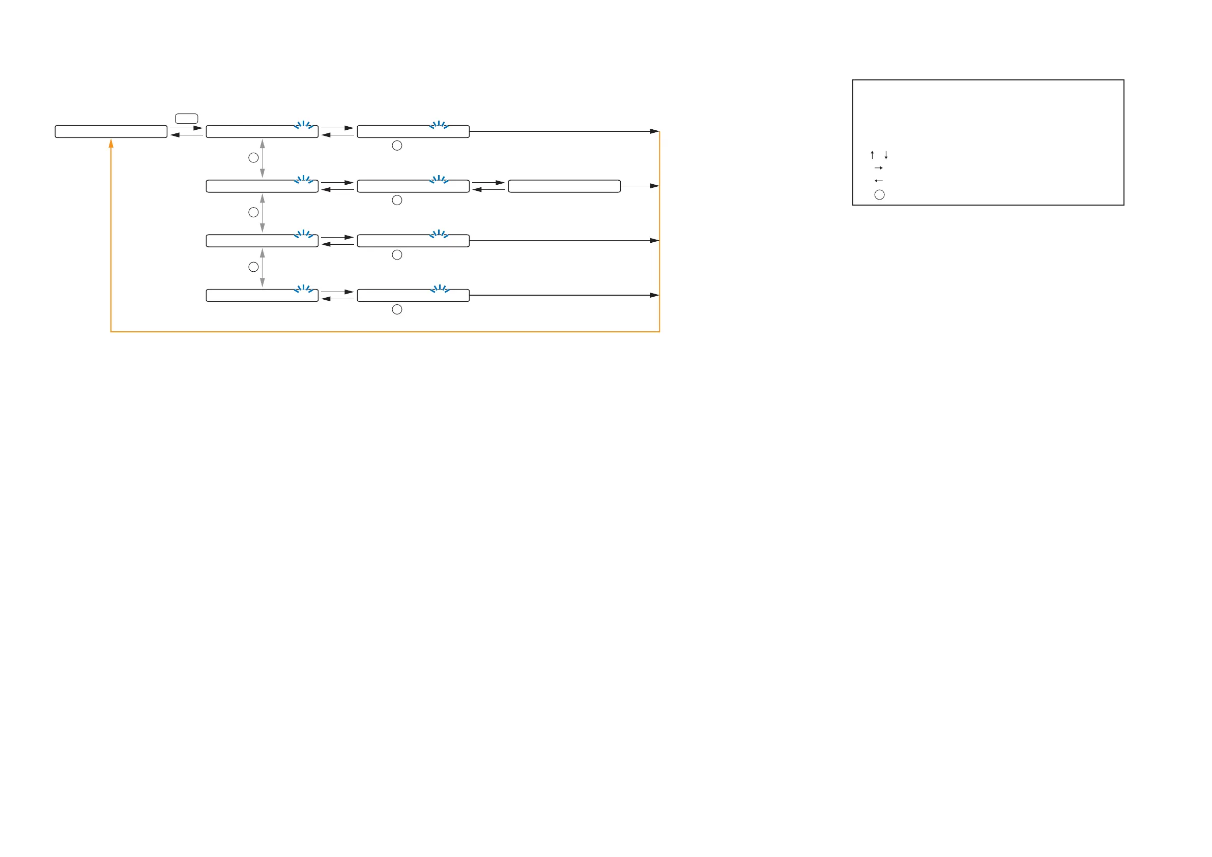
10.6. MEMORY Setting Flow Chart
0 1
-
S C E N E 1
Normal use state
MEMORY
S C E N E S E T T I N G L O A D
The screen display examples may differ from actual displays.
The on-screen indications shown in blue are variable parameters
by key operation.
The symbols in the figure represent the following key operation.
: Screen shift keys (up and down)
: Screen shift key (right) or ENTER key
: Screen shift key (left) or ESC key
: PARAMETER knob
P
(p.92-D1) (p.92-D2)
: 01 to 32SCENE
P
L O A D <
-
0 1 S C E N E 1
P
S C E N E S E T T I N G S A V E
(p.92-D1) (p.92-D3)
: 01 to 32SCENE
P
S A V E <
-
0 1 S C E N E 1 S A V E C O M P L E T E
P
S C E N E S E T T I N G E R A S E
(p.92-D1) (p.93-D4)
: 01 to 32SCENE
P
E R A S E <
-
0 1 S C E N E 1
P
S C E N E S E T T I N G P
-
O N
(p.92-D1) (p.93-D5)
: 01 to 32, LAST SCENESCENE
P
P O W E R O N <
-
LAST S C E N E