0 1
-
S C E N E 1
Normal use state
1
INPUT SELECT
I N 1
-
I N 1 : O F F
I N 1
-
-
-
-
-
-
-
-
I N 1
-
I N 1 : O N 0. 0
I-ON/OFF
P
or
IN
: +10 to -70, ∞ (0.5 dB steps)
To/from lowermost screen
(p.56-A1)
(p.56-A2)
1
INPUT SELECT
: Cycles meter display (FADER /LEVEL) below
the setting screen each time pressed.
: Selects characters to enter.
(Right shift key): Moves the cursor to the right.
P
P R E P A G I N G
-
O F F
(p.62-A24)
or : ON/OFF
P
I-ON/OFF
P A G I N G T I M E 3 0
(p.62-A27)
: 30 (sec), 10 (m)
P
: 01 to 32
P
: 01 to 32
P
: 01 to 12
P
M O D E => P A G I N G P O R T
(p.62-A25)
: RINGING SIGNAL, PAGING PORT
P
P R I O R I T Y 2
(p.62-A26)
: 1, 2, 3
P
D U C K E R
-
D E P T H O F F
(p.59-A13)
: OFF,
-
50,
-
40,
-
30,
-
20,
-
10, 0 (dB)
P
: 1 to 8
P
: 01 to 32
P
P A G I N G : M A N U A L
(p.63-A28)
P A G I N G : AUTO G R P 0 1 I N 1
-
> O U T 1
(p.63-A29)
(p.63-A30)
P A G I N G : I N 1
-
> O U T 1
P
P
P A G I N G : Z O N E G R O U P 1 G R P 0 1 I N 1
-
> O U T 1
(p.63-A31)
1 G R P 0 1 I N 1
-
> O U T 1
(p.63-A32)
1 G R P 0 1 I N 1
-
> O U T 1
(p.63-A33)
P A G I N G S Y N C O F F
P
: Selects OUT.
P
: Confirms the setting.
O-ON/OFF
P A G I N G S Y N C O N
(p.60-A18)
(p.60-A19)
S Y N C O U T C
-
O U T 0 1
: Selects OUT.
P
: Confirms the setting.
O-ON/OFF
G R P 0 1 I N 1
-
> M A N U
(p.63-A29)
To/from uppermost screen
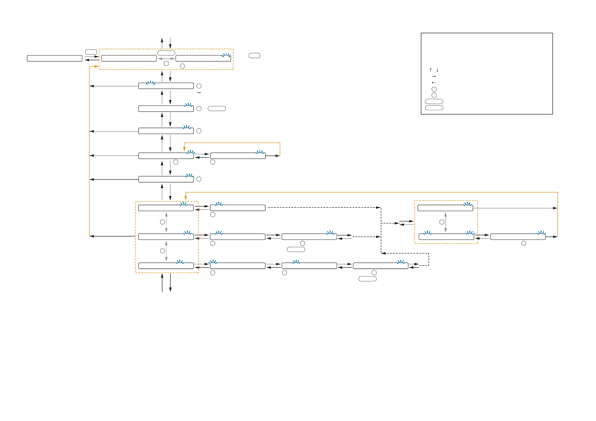
The screen display examples may differ from actual displays.
The on-screen indications shown in blue are variable parameters
by key operation.
The symbols in the figure represent the following key operation.
: Screen shift keys (up and down)
: Screen shift key (right) or ENTER key
: Screen shift key (left) or ESC key
: PARAMETER knob
: INPUT VOLUME knob
: Input channel ON/OFF key
: Output channel ON/OFF key
I-ON/OFF
O-ON/OFF
P
IN
10.2.2. Input setting flow chart for the channel on which the ZP-001T is used