Introduction
HiPer Pro Operator’s Manual
1-14
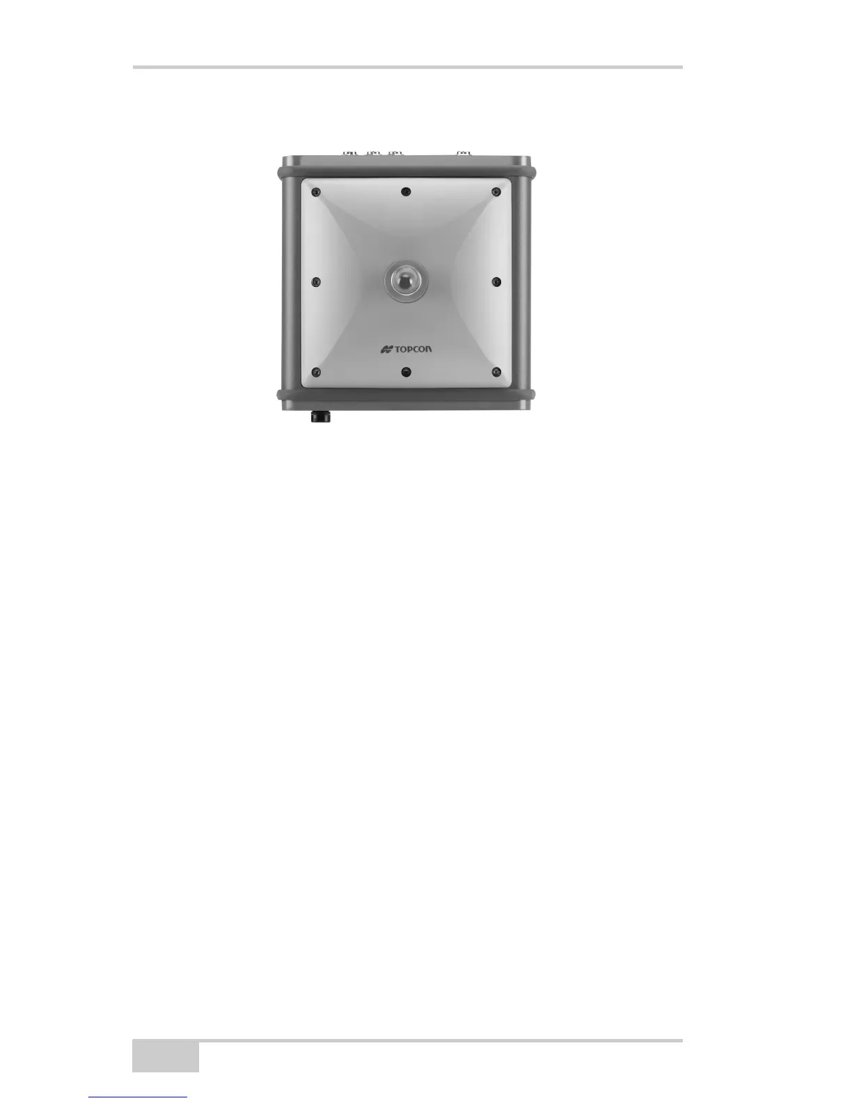
Figure 1-4. HiPer Pro Radome
Front Panel
Figure 1-5 on page 1-15 shows front panel components for the HiPer
Pro receiver:
• MINTER – The Minimum INTERface for the receiver consisting
of three keys and four, three-color LEDs. See “Using the
MINTER” on page 4-2 for descriptions and usages of the
MINTER components.
• Reset – This key performs a hard reset for both the receiver board
and the power board. Once this key is pressed, the controllers
governing the receiver and power boards reboot and the device
restarts.
• This key can be used to leave Zero Power Mode or if the receiver
does not respond to commands. See “Using the MINTER” on
page 4-2 for more information.
• Four serial ports:
– Port A used for communication between the receiver and a
controller or any other external device.
– Port B used internally to connect the receiver board and
Bluetooth module.