MINTER Configuration
P/N 7010-0681
2-19
MINTER Configuration
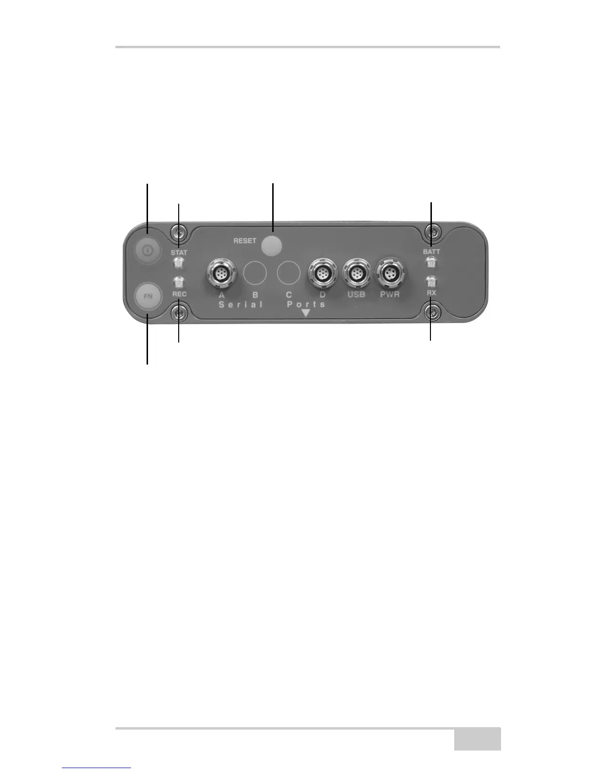
The Minimum INTERface (MINTER) consists of three keys (Power,
FN, and Reset) and four LEDs (STAT, REC, BATT, and RX) that
control and display the receiver’s operation (Figure 2-15).
Figure 2-15. MINTER
The MINTER performs numerous functions:
• Turn the receiver on or off, put it in either Sleep mode or Zero
power mode.
• Turn data recording on or off (FN key).
• Change the receiver’s information mode.
• Show the number of GPS (green) satellites being tracked (STAT
led).
• Show data recording status (REC led).
• Show each time data is recorded to internal memory (REC led).
• Show the status of post-processing mode (static or dynamic)
when performing a Post-Processing Kinematic survey with the
help of FN key (REC LED).
• Show the status (high charge, intermediate charge, or low charge)
of the battery (BATT LED).
Power Button
Reset
BATT
(battery LED)
RX
(modem status LED)
STAT (status LED)
FN (function/recording button)
REC (recording LED)