Introduction
X63/X62 Installation and Calibration Manual
1-4
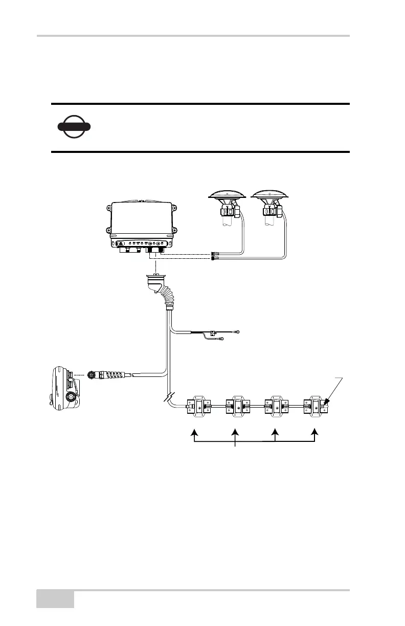
Figure 1-4 shows the basic cabling connections for the X63/X62
system. When installing components, use the Topcon supplied fuse or
fused power from the machine of the same rating.
Figure 1-4. Basic Cable Connections for X63
System ground must be connected to the frame side
of the ground disconnect switch, not directly to the
negative battery terminal.
ATTACH TO
UPPER CONNECTOR
AUX GPS
ANTENNA
MAIN GPS
ANTENNA
TS-1 TILT SENSORS
BODY BOOM STICK BUCKET
40-PIN
CONNECTOR
"A"
-
+
VOLTAGE SUPPLY
(SWITCHED OR
UNSWITCHED IS
ACCEPTABLE)
GROUND TO CHASSIS
15 AMP
IN-LINE FUSE
REQUIRED
MC-R3 CONTROLLER
GX-60 DISPLAY
SENSOR
TERMINATOR