PTOSwitch
g191000
Figure163
1.PTOswitch2.Controlarm
g191001
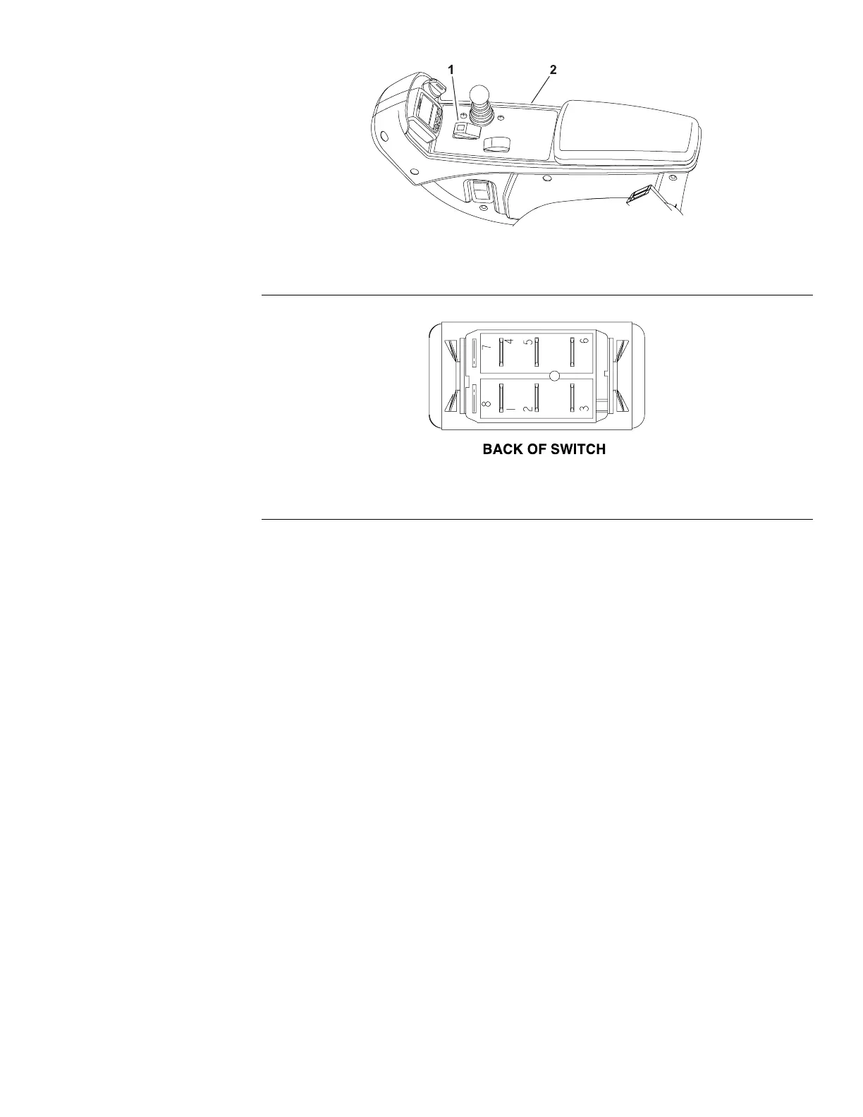
Figure164
ThePTOswitchislocatedonthecontrolarm(Figure163)andallowsthecutting
deckstooperatewhenthefrontoftheswitchispressed.Anindicatorlightonthe
switchidentieswhenthePTOswitchisengaged.
TheTECmonitorsthepositionofthePTOswitch(upordown).Usinginputsfrom
thePTOswitchandotherswitchesintheinterlocksystem,theTECcontrolsthe
energizingofthehydraulicsolenoidvalvesusedtodrivethecuttingdeckmotors.
Note:T oengagethePTO,theseathastobeoccupied,themowspeedlimiter
hastobeintheMOWposition,andthecuttingdeckshavetobefullylowered.
TestingthePTOSwitch
1.Parkthemachineonalevelsurface,lowerthecuttingdecks,settheparking
brake,andshutofftheengine.
2.BeforeyoudisconnectthePTOswitchfortesting,ensurethatyoutestthe
switchanditscircuitwiringasaTECelectricalinputwiththeInfoCenter
display;refertoUsingtheInfoCenterDisplayforTroubleshooting(page
5–26).
3.IftheInfoCenterveriesthatthePTOswitchandcircuitwiringarefunctioning
correctly,nofurtherswitchtestingisnecessary.
4.IftheInfoCenterdeterminesthatthePTOswitchandcircuitwiringarenot
functioningcorrectly,proceedwiththetest.
5.RemovethecontrolarmcoverstogetaccesstothePTOswitch;referto
DisassemblingtheControlArm(page6–24).
6.EnsurethatthekeyswitchisintheOFFposition.Disconnectthewireharness
electricalconnectorfromthePTOswitch.
7.ThePTOswitchterminalsareidentiedinFigure164andthecircuitryofthe
switchisshownintheCircuitLogicTable(page5–54).Withtheuseofa
Groundsmaster
®
4300-D
Page5–53
ElectricalSystem:TestingtheElectricalComponents
16226SLRevC

 Loading...


