4 Replacement Procedures 4.15 Cover assembly and Base assembly
4-42 [CONFIDENTIAL] TECRA A9/TECRA S5/TECRA P5/Satellite Pro S200 Maintenance Manual (960-633)
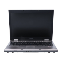
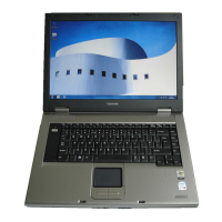
Installing the Cover assembly and Base assembly
To install the cover assembly and base assembly, follow the steps below and refer to Figure
4-24 to 4-25.
1. Place the cover assembly on the base assembly and engage the latches.
2. Connect the LCD cable, speaker cable and fingerprint sensor cable to the
connector CN5000, CN6170 and CN 9550 on the system board.
3. Secure the cover assembly with the following screws.
• M2.5×6B FLAT HEAD screw ×3
4. Close the display and turn over the computer.
5. Connect the USB cable to the connector CN4612 on the system board.
6. Secure the cover assembly with the following screws.
• M2.5×6B FLAT HEAD screw ×8 (“6” in the figure 4-24)
• M2.5×16B FLAT HEAD screw ×5 (“16” in the figure 4-24)

 Loading...