4.20 System board 4 Replacement Procedures
1. Install the modem jack and USB board into the slot.
2. Arrange the modem jack cable and USB board cable to the guides and stick the
insulator in place.
3. Install the system board while engaging two latches.
CAUTION: When installing the system board, make sure that the wireless
communication switch is engaged to the guide.
4. Install the DC-IN jack into the slot.
5. Install the HDD cable into the slot and stick the glass tape in place.
6. Connect the DC-IN jack cable to the connector CN8800 on the system board.
7. Connect the SmartCard unit cable to the connector CN2170 on the system board.
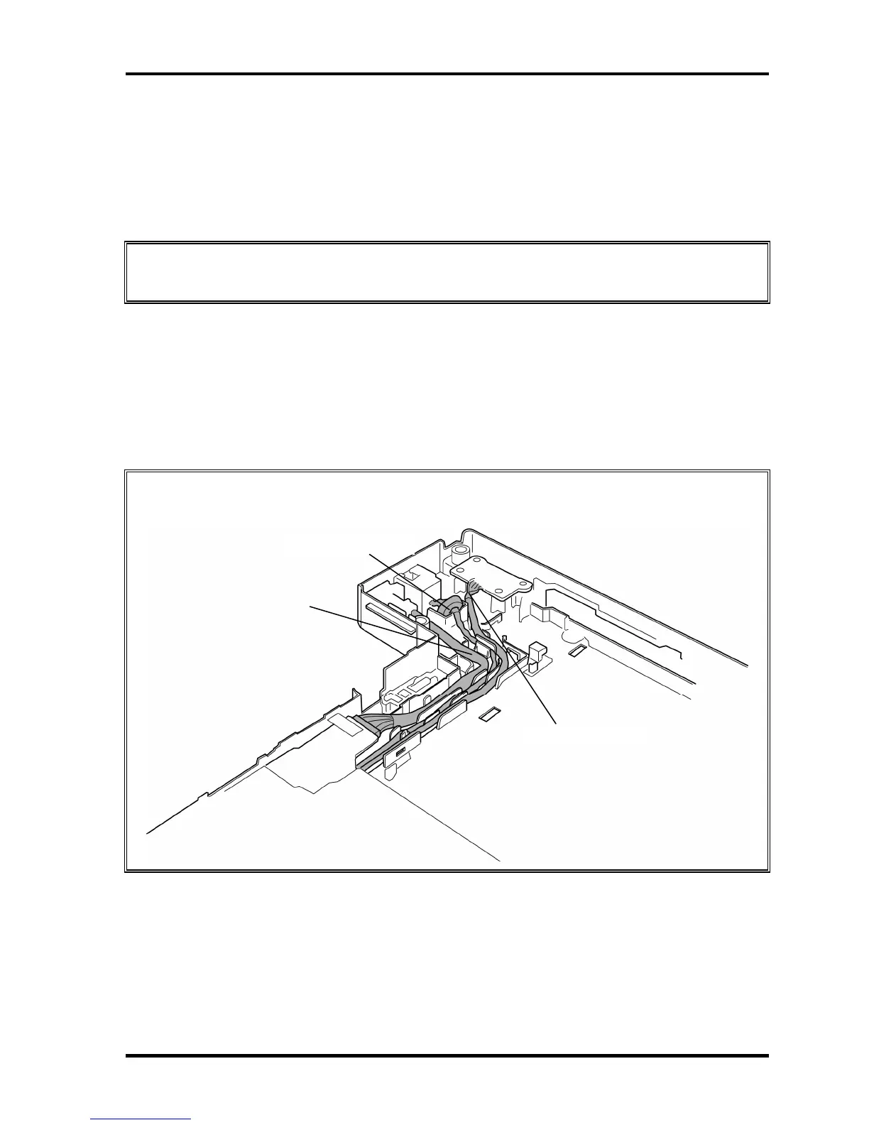
CAUTION: Arrange the DC-IN jack cable, modem jack cable and USB board cable as
shown in the figure below.
Modem jack cable
DC-IN jack cable
USB board cable
8. Install the cable holder to the slot while engaging the latches.
TECRA A9/TECRA S5/TECRA P5/Satellite Pro S200 Maintenance Manual (960-633) [CONFIDENTIAL] 4-59

 Loading...