EasyManuals Logo

Toshiba Tosvert VF-S15 User Manual

Toshiba Tosvert VF-S15
394 pages
To Next Page IconTo Next Page
To Previous Page IconTo Previous Page
Page #266 background imageLoading...
Page #266 background image
E6582175
G-7
7
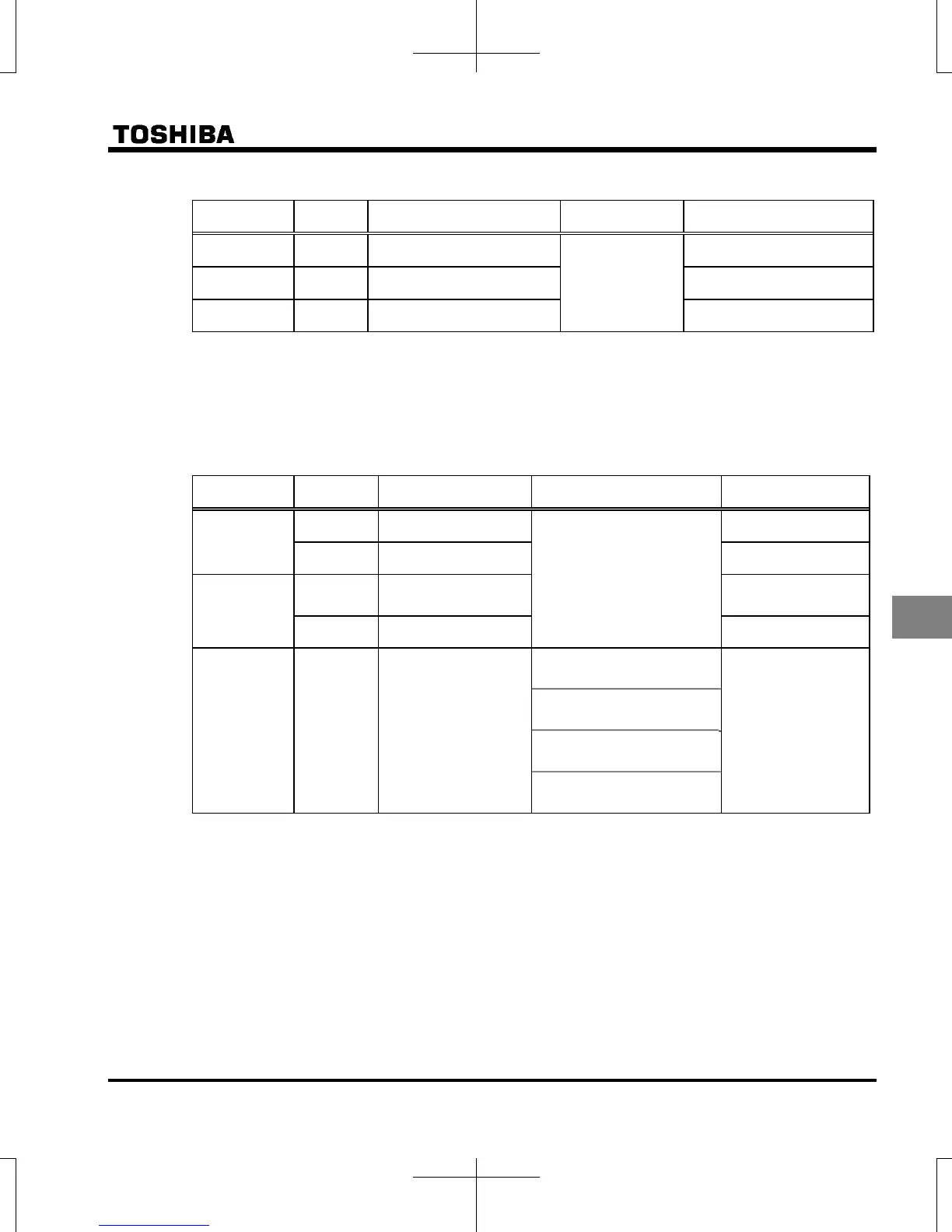
Assign one type of function to an output terminal
Terminal
symbol
Title Function Adjustment range Default setting
RY-RC

Output terminal selection 1A
0 - 255
4 (Low-speed detection
signal)
OUT

Output terminal selection 2A
6 (Output frequency
attainment signal)
FL
(A, B, C)

Output terminal selection 3 10 (Fault signal)
Note 2) When assigning 1 type of function to the RY-RC terminal, set only .
Leave parameter  as the default setting ( = ).
Note 3) When assigning 1 type of function to the OUT terminal, set only .
Leave parameter  as the default setting ( = ).
Assign two types of functions to the output terminal (RY-RC, OUT)
Terminal
symbol
Title Function Adjustment range Default setting
RY-RC

Output terminal
selection 1A
0 - 255
4 (Low-speed
detection signal)

Output terminal
selection 1B
255 (Always ON)
OUT

Output terminal
selection 2A
6 (Output frequency
attainment signal)

Output terminal
selection 2B
255 (Always ON)
RY-RC,
OUT

Output terminal logic
selection
0:  and 
 and 
0
1:  or 
 and 
2:  and 
 or 
3:  or 
 or 
Note 4)  and  are active only when  = : Logic output (default).
Function is inactive when  = : Pulse train output is set.

Table of Contents

Other manuals for Toshiba Tosvert VF-S15

Questions and Answers:

Question and Answer IconNeed help?

Do you have a question about the Toshiba Tosvert VF-S15 and is the answer not in the manual?

Toshiba Tosvert VF-S15 Specifications

General IconGeneral
CategoryInverter
Control MethodV/f control, Sensorless vector control
Cooling MethodForced air cooling
ModelTosvert VF-S15
Protection FeaturesOvercurrent, Overvoltage, Undervoltage, Overheat
Communication OptionsModbus RTU
Overload Capacity150% for 1 minute
Braking UnitBuilt-in braking transistor
Output Voltage3-Phase, same as input voltage
Operating Temperature-10 to +50°C (14 to 122°F)
Storage Temperature-20 to 65°C (-4 to 149°F)
Humidity5 to 95% RH (non-condensing)
AltitudeUp to 1000m above sea level
Input Voltage3-Phase 200 to 240 VAC, 3-Phase 380 to 480 VAC
WeightVaries depending on model (e.g., 0.8 kg to 16 kg)

Related product manuals