User Guide 148
Configuring 802.1Q VLAN Configuration Example
3.3 Network Topology
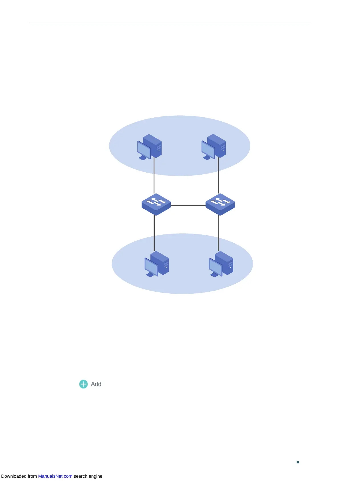
The figure below shows the network topology. Host A1 and Host A2 are in Department A,
while Host B1 and Host B2 are in Department B. Switch 1 and Switch 2 are located in two
different places. Host A1 and Host B1 are connected to port 1/0/2 and port 1/0/3 on Switch
1 respectively, while Host A2 and Host B2 are connected to port 1/0/6 and port 1/0/7 on
Switch 2 respectively. Port 1/0/4 on Switch 1 is connected to port 1/0/8 on Switch 2.
Figure 3-1 Network Topology
VLAN 10
VLAN 20
Host A1 Host A2
Host B1
Host B2
Switch 1
Switch 2
Fa1/0/2
Fa1/0/3
Fa1/0/4
Fa1/0/6
Fa1/0/7
Fa1/0/8
Demonstrated with T1500-28PCT, the following sections provide configuration procedure
in two ways: using the GUI and using the CLI.
3.4 Using the GUI
The configurations of Switch 1 and Switch 2 are similar. The following introductions take
Switch 1 as an example.
1) Choose the menu L2 FEATURES > VLAN > 802.1Q VLAN > VLAN Config and
click to load the following page. Create VLAN 10 with the description of
Department_A. Add port 1/0/2 as an untagged port and port 1/0/4 as a tagged port to
VLAN 10. Click Create.
Downloaded from ManualsNet.com search engine
 Loading...