Configuration Example
User Guide 797
6
Configuration Example
6.1 Network Requirements
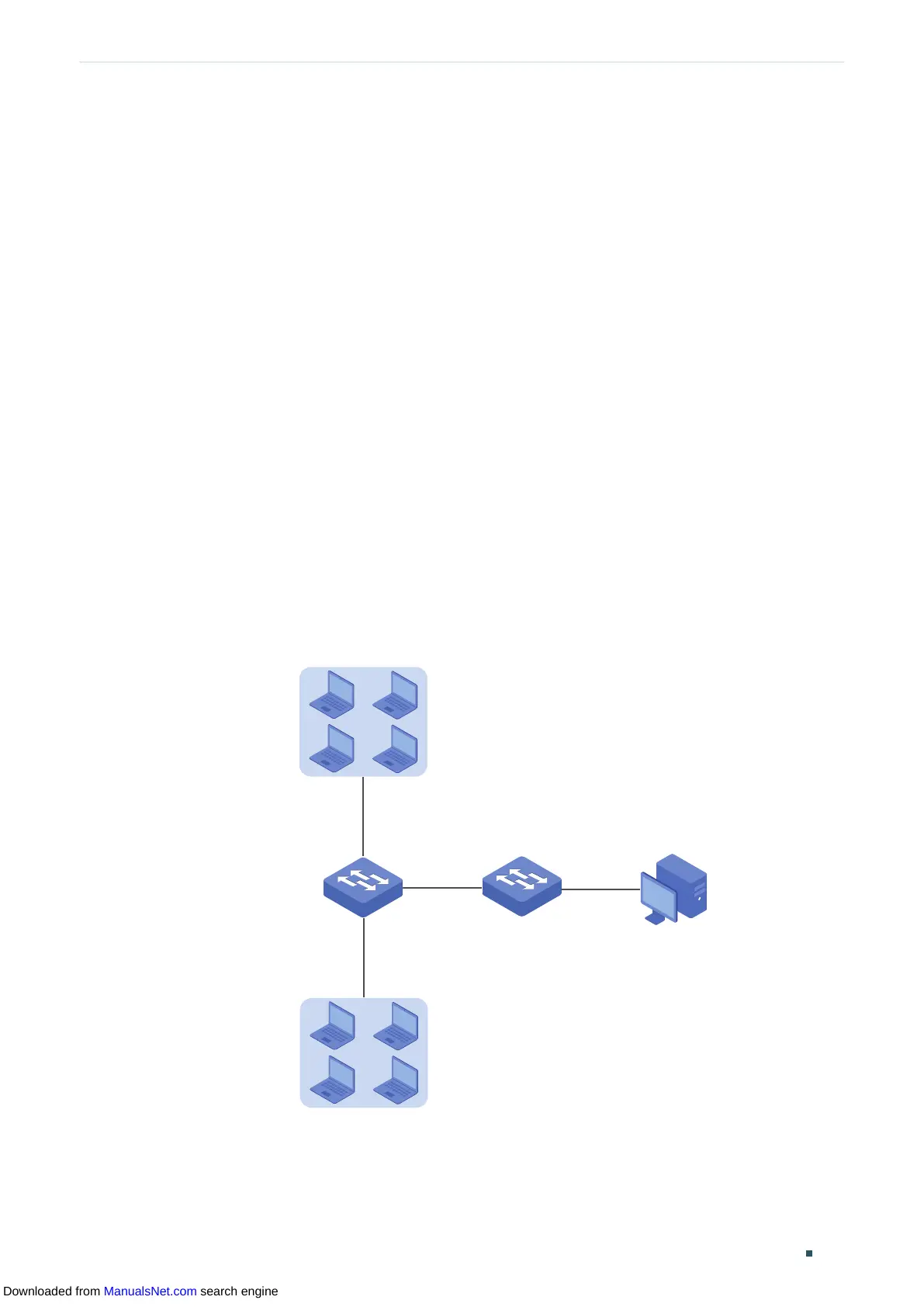
The following figure shows the network topology of a company. The company has
requirements as follows:
1) Monitor storm traffic of ports 1/0/1 and 1/0/2 on Switch A, and send notifications to the
NMS when the actual rate of broadcast, multicast or unknown-unicast packets exceeds
the preset threshold.
2) Monitor the traffic of ports 1/0/1 and 1/0/2 on Switch A, and regularly collect and
save data for follow-up checks. Specifically, Switch A should notify the NMS when the
number of packets transmitted and received on the ports during the sample interval
exceeds the preset rising threshold, and should record but not notify the NMS when
that is below the preset falling threshold.
The NMS host with IP address 192.168.1.222 is connected to the core switch, Switch B.
Switch A is connected to Switch B via port 1/0/3. Port 1/0/3 and the NMS can reach one
another.
Figure 6-1 Network Topology
Gi1/0/1
NMS
Switch B
Switch A
IP: 192.168.1.222
Gi1/0/2
Gi1/0/3
Downloaded from ManualsNet.com search engine
 Loading...