100
CDHH-SVX003C-EN
continued stable operation of the chiller is always more
important than the regeneration of the carbon tank.
Therefore, the following rules apply:
1. If the Daily Pump-out Limit is disabled, a regeneration
cycle may not be initiated, regardless of the value of the
remaining carbon capacity.
Also, if the Daily Pump-out Limit is disabled during a
regeneration cycle, the regeneration cycle must be
terminated.
2. When the remaining carbon capacity is less than
80 percent, a regeneration cycle will be initiated at the
next opportunity when the chiller is running (after the
chiller has started and no pump-out minutes have
accumulated for the previous 60 minutes).
3. If there is no opportunity to purge as indicated by Rules
1 and 2 and the remaining carbon capacity is less than
50 percent, a regeneration cycle will be initiated at the
best opportunity when the chiller is shutdown (and no
pump-out minutes have accumulated for the previous
60 minutes).
4. If there is no opportunity to regenerate as indicated by
Rules 1, 2, and 3 and the carbon capacity drops below
0 percent, then a regeneration cycle is initiated.
5. Note that, if at any time during the regeneration cycle
the chiller is running and shuts down or if the chiller is
off and starts up, then the regeneration cycle is
continued.
Carbon Tank Regeneration Sequence
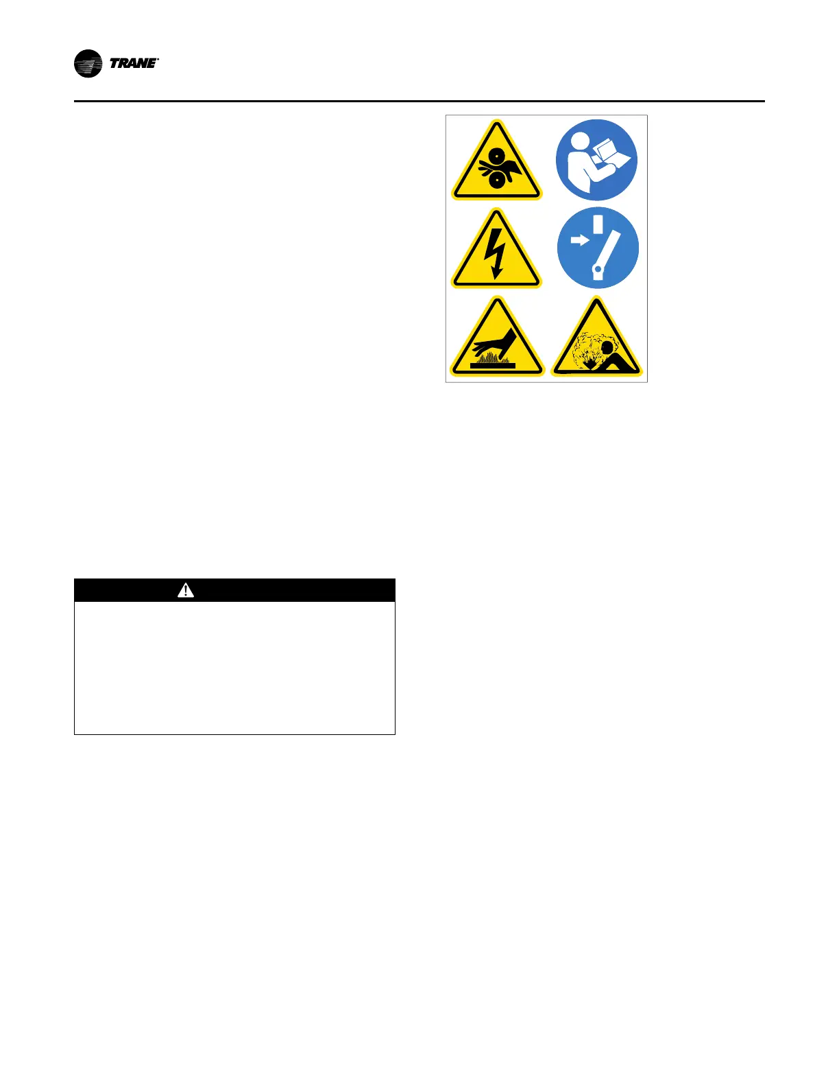
WARNING
Hazardous Voltage!
Failure to disconnect power before servicing could
result in death or serious injury.
Disconnect all electric power, including remote
disconnects before servicing. Follow proper lockout/
tagout procedures to ensure the power can not be
inadvertently energized. Verify that no power is
present with a voltmeter.
Note: Graphic labels (shown above) are used for CE
application only.
Important:
• Before servicing, disconnect all power
sources and allow at least 30 minutes for
capacitors to discharge.
• All electrical enclosures—unit or remote—
are IP2X.
If the purge controller determines that carbon tank
regeneration is desired and is allowed, the purge controls:
1. Disable the purge refrigeration circuit and the pump-out
solenoid valve.
2. Open the regeneration solenoid valve and turn on the
carbon tank heater.
3. Monitor the carbon temperature until it reaches the
regeneration temperature value of 240°F (115.6°C),
and control within a ±10°F (5.6°C) dead band for
15 minutes (this step should take approximately
three hours).
• If the carbon tank temperature does not increase
more than 25°F (13.9°C) in the first two hours, the
controller generates a non-latching diagnostic,
Carbon Regeneration Temperature Too Low, and
indicates a status of Carbon Regeneration
Disabled. The purpose of this diagnostic is to
identify a failed heater or temperature sensor. It
prevents automatic regeneration from occurring,
but a service technician can initiate a manual
regeneration for testing purposes. All other purge
algorithms continue to function.
• If the carbon tank temperature does not reach the
regeneration temperature setpoint minus 30°F
(16.7°C) within four hours, the controller generates
a non-latching diagnostic Purge Carbon
Regeneration Temperature Not Satisfied. The
purpose of this diagnostic is to identify a failing
insulation system. All purge functions remain
active.
Start-up and Shutdown