Maintenance and repair
Pneumatic block diagrams
94
Operating instructions: Outfeed conveyor TS 4800
Version 3.6ENG, 27.01.2020
Pneumatic block diagrams
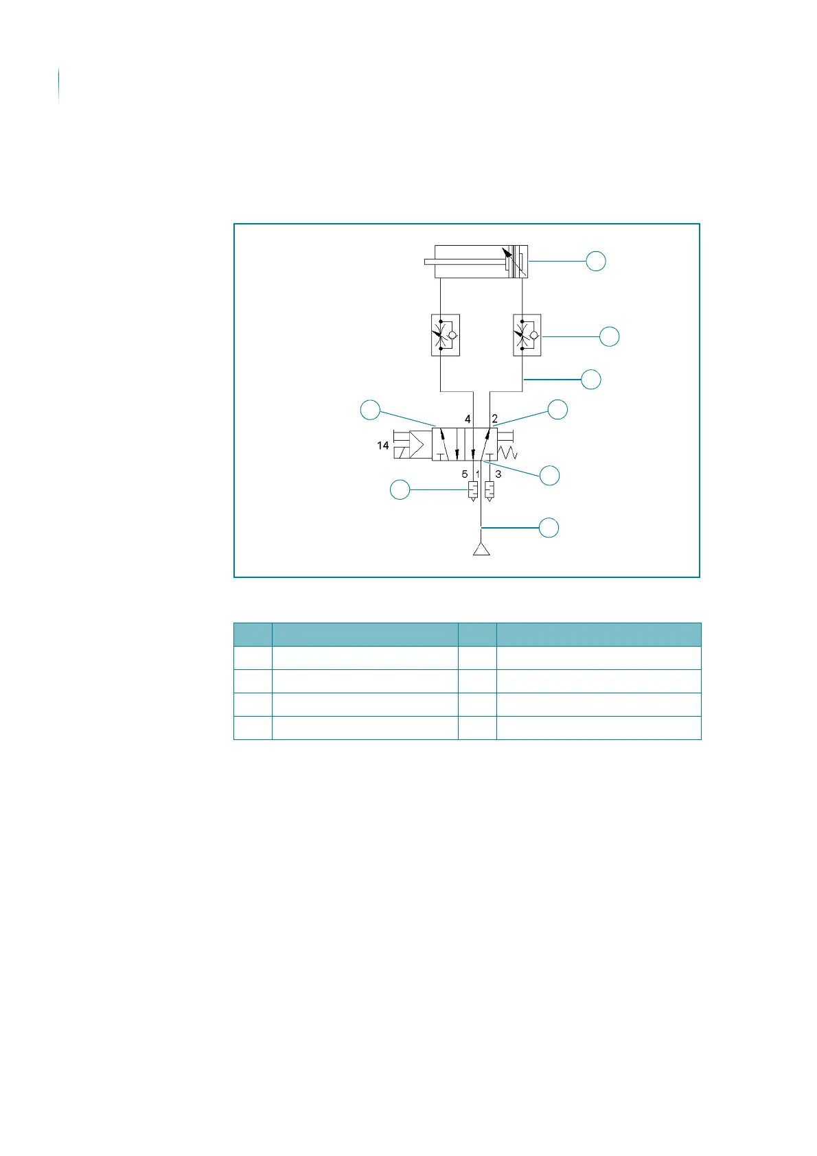
The following figures show the pneumatic block diagrams for the swivel roller
assembly control.
TS 4800 pneumatic block diagram, individual control
Key to illustration
No. Name No. Name
1 Pneumatic cylinder 5 L screw connection
2 One-way restrictor 6 L screw connection
3 Solenoid valve 7 Plastic hose
4 Silencer 8 Plastic hose
 Loading...