Transportation and erection
Pneumatic block diagram
46
Operating instructions: Outfeed conveyor TS 4800
Version 3.6ENG, 27.01.2020
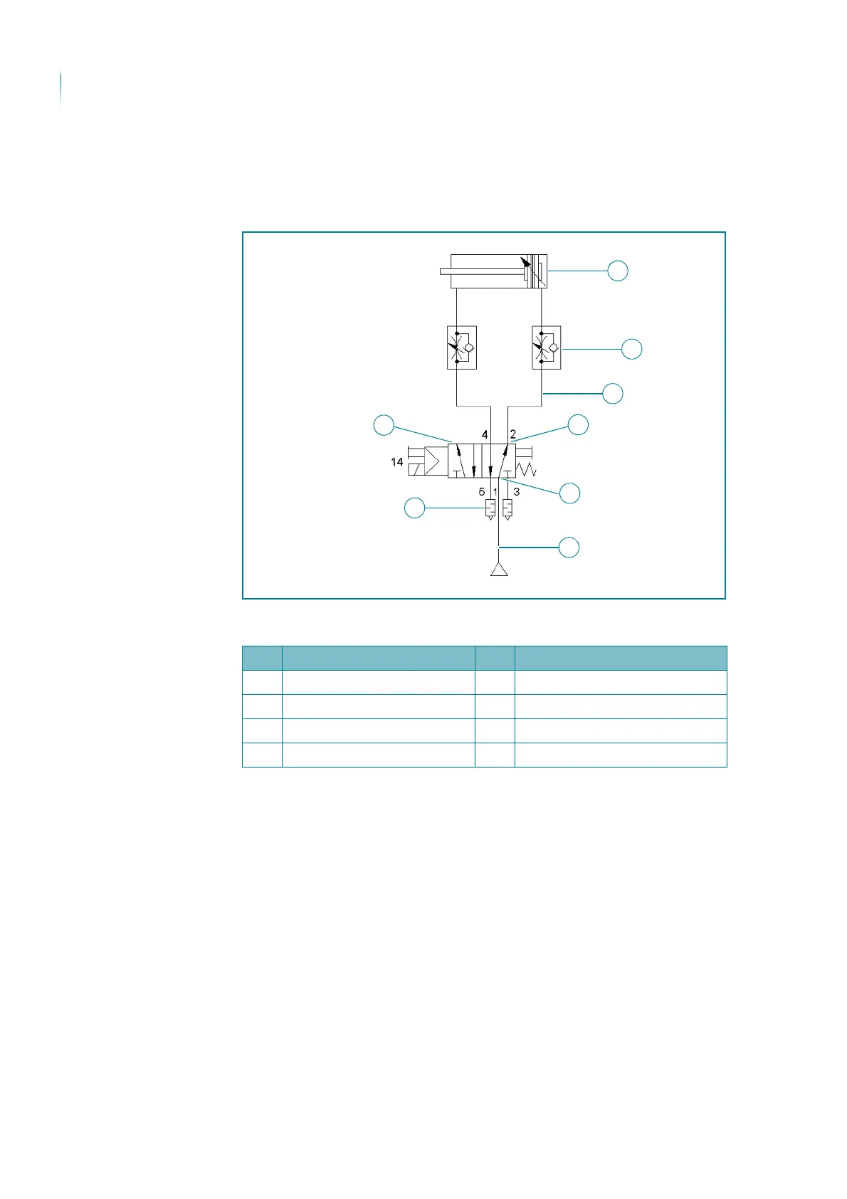
Pneumatic block diagram
The following figures show the pneumatic block diagrams for the swivel roller
bar control.
TS 4800 Pneumatic block diagram, individual control
Picture illustration
No. Designation No. Designation
1 Pneumatic cylinder 5 L screw connection
2 Throttle check valve 6 L screw connection
3 Solenoid valve 7 Plastic hose
4 Silencer 8 Plastic hose