CHAPTER 4
Configuring the CPC
4-1
This chapter describes how to enter the Configuration mode and
select the various microprocessor outputs and controls. It also
explains how to calibrate the D/A
and A/D converters and the flow
meter.
Enabling the Configuration Mode
To enable the Configuration mode, first set the red paddle switch
on the Display printed circuit (PC) board to “enable.” The board is
shipped in the “disable” position so that you cannot unknowingly
alter the calibration and setup configuration.
1. Remove power from the CPC and from any instruments
connected to the CPC.
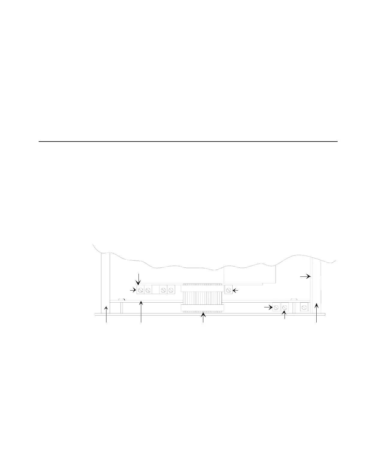
2. Remove the top cover from the CPC. The Display board is next to
the front panel, as shown in Figure 4-1.
Display
Board
Ribbon
Cable
Power
Supply
Board
Analog
Board
Side
Rod
RA1
RA6
RA1
RA2
Side
Rod
Display PC Board
Figure 4-1
Location of PC Boards and Potentiometers