D301087 0308 - BL20 CANopen 6-15
Power Supply
6
Cross-connecting relay module roots is achieved by the use of
jumpers. The corresponding wiring diagram including the jumpers
can be found in chapter 4.
Direct Wiring of Relay Modules
As well as the options mentioned above, relay modules can be wired
directly. In this case, base modules without C-rail connections
should be chosen to guarantee the potential isolation to the
adjoining modules.
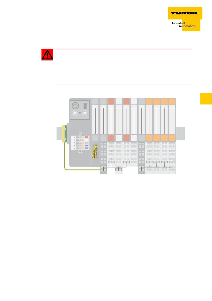
Attention
When relay modules are planned and the C-rail is used for a com-
mon voltage supply, a further power distribution module must be
used for the potential isolation to the following modules. The C-rail
can only again be used as a PE following potential isolation.
Figure 12:
Using the C-rail as
protective earth
and for the power
supply with relay
modules
Gateway
23
22
21
13
12
11
23 23
22 22
21 21
13 13
12 12
11 11
24 24
23 23
22 22
21 21
14 14
13 13
12 12
11 11
24
23
22
21
14
13
12
11
24
23
22
21
14
13
12
11
24
23
22
21
14
13
12
11
24
23
22
21
14
13
12
11
24
23
22
21
14
13
12
11
TS
Gateway
PE
terminal
BR
SBBC
2 DO
SBC
2 DI
SBBC
2 DO
SBC
2 DI
SBB
PF NCNO
SBCSSBCS
NO
SBCS
NC
SBCS
C-rail (24 V DC)C-rail (PE)
SBBC