Guidelines for Electrical Installation
D301087 0308 - BL20 CANopen7-14
A potential compensation cable must have the following character-
istics:
Low impedance. In the case of compensation cables that are
routed on both sides, the compensation line impedance must be
considerably smaller than that of the shield connection (max.
10 % of shield connection impedance).
Should the length of the compensation cable be less than 200 m,
then its cross-section must be at least 16 mm
2
/ 0.025 inch
2
. If
the cable length is greater than 200 m, then a cross-section of at
least 25 mm
2
/ 0.039 inch
2
is required.
The compensation cable must be made of copper or zinc coated
steel.
The compensation cable must be connected to the protective
conductor over a large surface area and must be protected
against corrosion.
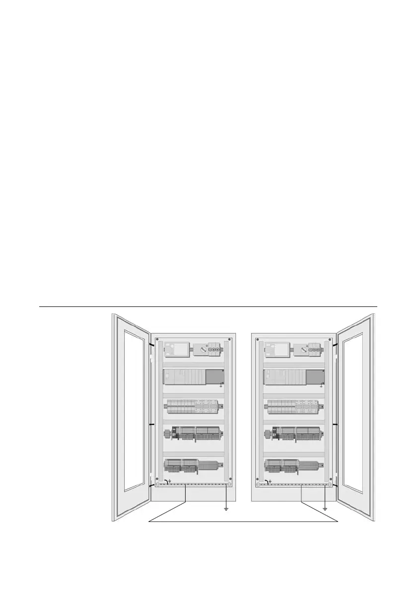
Compensation cables and data cables should be routed as close
together as possible, meaning the enclosed area should be kept
as small as possible.
Figure 16:
Potential com-
pensation be-
tween switchgear
cabinets