Page 3-14
Maintenance 3.10 - Hydraulics
TM12 Work Platform - European
D
RIVE
R
ELIEF
V
ALVE
A
SSEMBLY
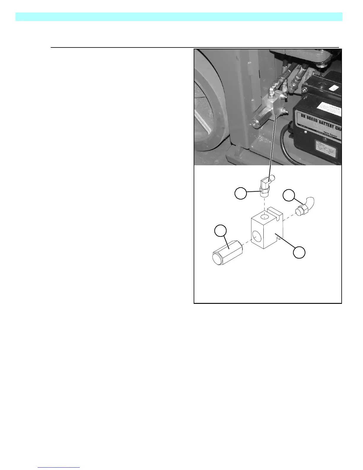
Figure 3-13:
Drive Relief Valve
The Drive Relief Valve Assembly is
located behind the panel on the left
side of the machine, toward the front.
SETTING DRIVE RELIEF
V
ALVE
P
RESSURE
1. Operate the work platform for 10-
15 minutes to bring the hydraulic
oil up to normal operating tem-
perature.
2. Move machine so the front is
against a wall or other unmov-
able object.
3. Install gauge in the gauge port of
the hydraulic manifold (see
Figure 3-15).
4. Loosen locknut or remove cover
on the Drive Relief Valve and
turn adjusting screw counter-
clockwise two full turns.
5. While one person drives the
machine forward against the
wall, slowly turn the Drive Relief
Valve adjusting screw clockwise
to increase the pressure until the
gauge reads 207 bar (3000 psi).
6. Tighten locknut or replace Drive
Relief Valve cover and torque to
8 Nm (6 Ft/Lbs).
7. Remove gauge and replace cap.
Left Side, Panel Off
3
4
2
1. Valve Block
2. Drive Relief Valve
(torque to 54 Nm [40 ft. lbs.])
3. Hose Fitting, 90°
4. Hose Fitting, Straight
1

 Loading...


