Page 3-29
Maintenance 3.16 - Motor Controller and I/O Board Dip Switch Settings
TM12 Work Platform - European
3.16 M
OTOR
C
ONTROLLER AND
I/O B
OARD
D
IP
S
WITCH
S
ETTINGS
NOTE: - Before dip switch settings will take effect, power must be disconnected or Emergency Stop
switches must be depressed.
- Refer to Section 4 for diagnostics.
C
ONTROLLER
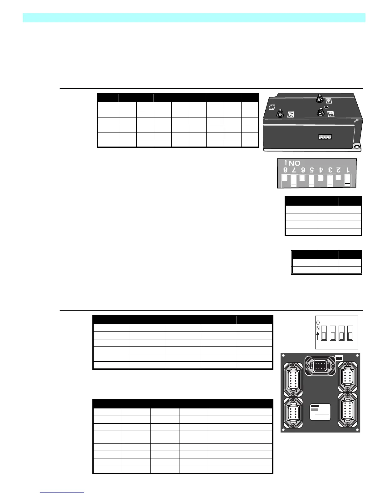
Figure 3-26:
Controller
The above table shows the default dip switch settings on
the controller box when the machine leaves the factory.
The following adjustments may be made to these set-
tings:
Switches 3 & 4 determine the elevated “creep” speed. If the
machine does not operate at the specified speed at the
default settings, use the following table to adjust the dip
switch settings
Switches 5 & 6 determine the deceleration time. Switch 5 is
for the deceleration rate while the platform is lowered.
Switch6isfortheelevatedrate.
I/O (C
IRCUIT
)B
OARD
Figure 3-27:
I/O Board
The above table shows the default dip switch settings on the I/O
board when the machine leaves the factory. Switches three and
four work together to determine the optional alarm settings
.
1 2 3 4 5 6 7 8
TM12 off off off on off off off on
MX15/19 off on off on off on off on
X/20N on off off on off off off on
X20W on on off on off off off on
X26/31 on on off on off off off on
SL20 on off off on off off off on
.
3 4
1(slowest) off off
2onoff
3 (default) off on
4 (fastest) on on
Decel 5 6
.24 sec. off off
1.27 sec. on on
1 2 3 4
TM12 off off off off
MX15/19 off off off off
X/20N off off off off
X20W off off off off
X26/31 off off off off
SL20 off off off off
1 2 3 4 Result
on Two Speed Mode (not used)
off Proportional Control
on not used
off
Depression Mechanism extends
when platform is raised
off off Down alarm only
on off Down and Reverse alarm
off on Drive and Down alarm
on on All Motion alarm
1234
8765
1234
8765
1234
12 11 10 9
56
87
1234
12 11 10 9
56
87
1234
8765
4321
Part
No.
Serial
No.
4321

 Loading...


