Page 3-28
Maintenance 3.15 - Controls
TM12 Work Platform - European
C
HASSIS
C
ONTROLS
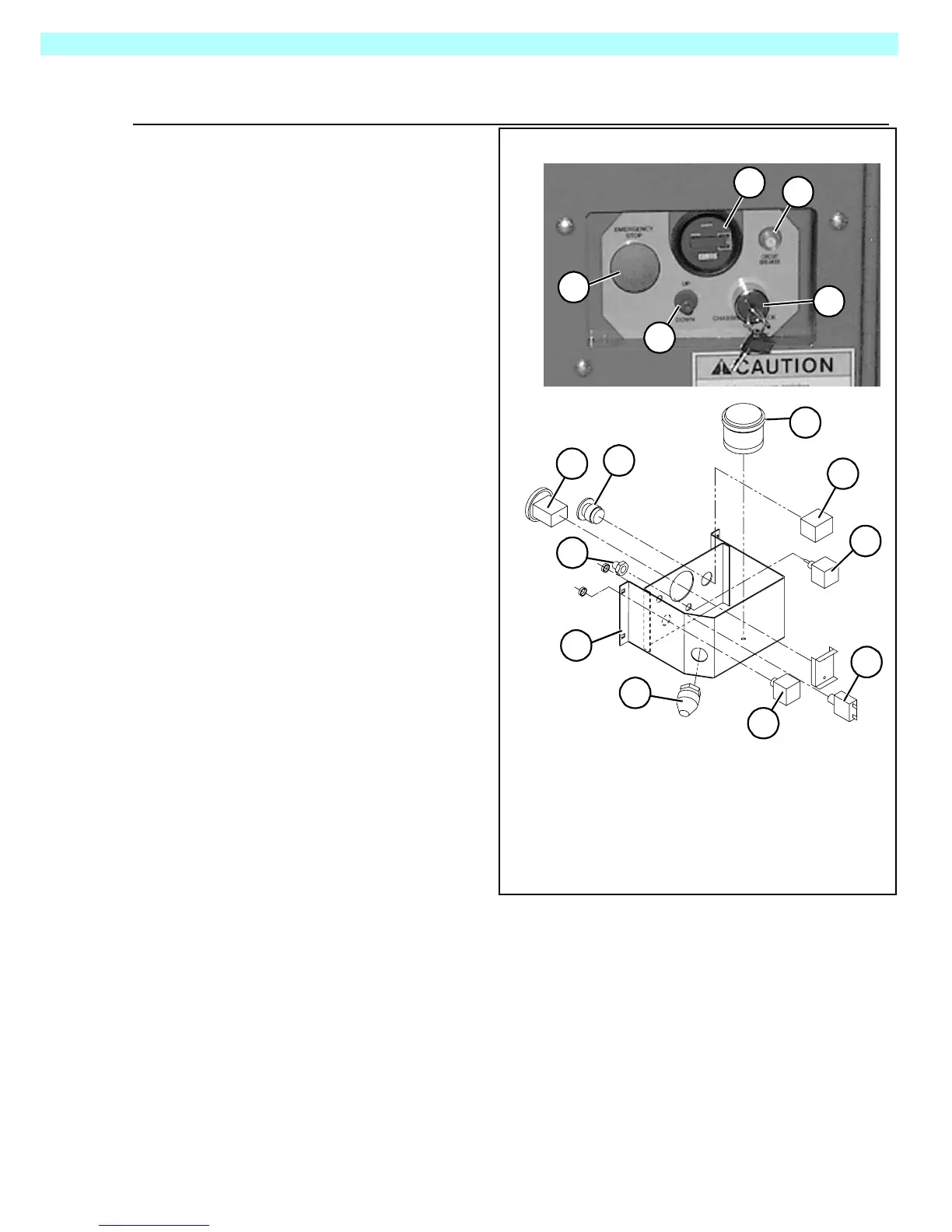
Figure 3-25:
Chassis Controls
The chassis control assembly is
mounted on the inside of the chassis
door, to the left of the Hydraulic tank.
It is secured to the door with Four
carriage bolts (1/4-20UNC x 3/4).
Right Side Door
1
2
6
2b
3
7
8
3
1
4
2
4
4b
5
5
1. Hour Meter/Voltage Indi-
cator
2.
Mushroom Emergency
Stop Switch
2b.
E-Stop Switch Contact
3.
Key Chassis/Platform
Selector Switch
4.
Up/Down Toggle Switch
4b. Boot Switch Cover
5. Circuit Breaker
6. Alarm, Dual Tone
7. Connector Cable, 3/4”
8. Box Weldment

 Loading...


