Page 3-19
Maintenance 3.11 - Cylinder Repair
TM12 Work Platform - European
D
EPRESSION
C
YLINDER
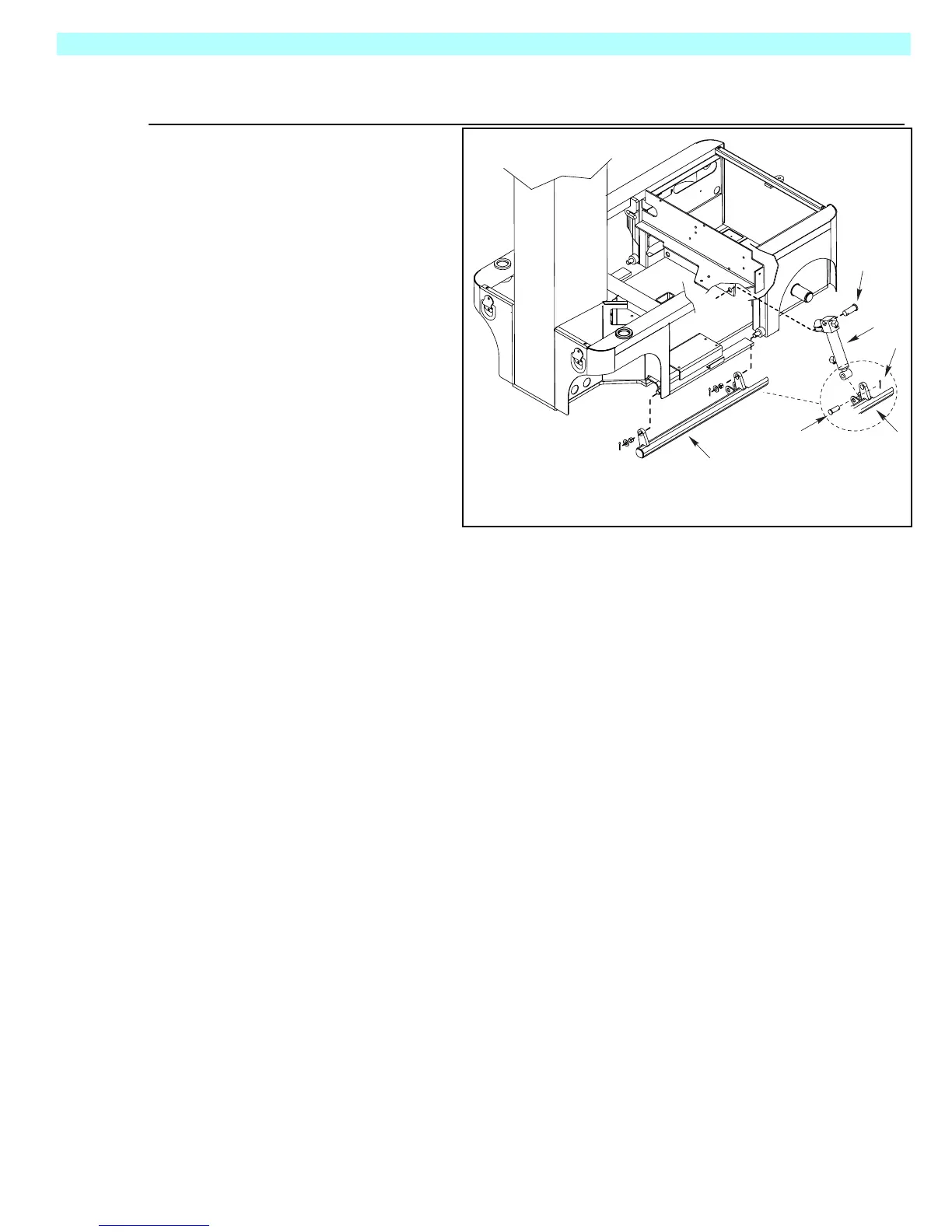
Figure 3-16:
Depression Cylinder Remove & Replace
REMOVAL
1. Mark and disconnect
the hose assemblies
from the cylinder fit-
tings and immediately
cap the openings to pre-
vent foreign material
from entering.
2. Place a support under
the depression guard.
3. Remove the cotter pins
from the pivot pins.
4. Remove the pivot pins
while supporting the cyl-
inder.
5. Remove the cylinder.
REPAIR
Reference:•
“3.11 Cylinder Repair” on Page 3-18
Depression Cylinder Seal Kit, Part Number: 065970-011
I
NSTALLATION
Installation is reverse of removal.
1
2
3
4
4
2
1. Depression Cylinder
2. Pivot Pin
3. Cotter Pin
4. Depression Guard

 Loading...


