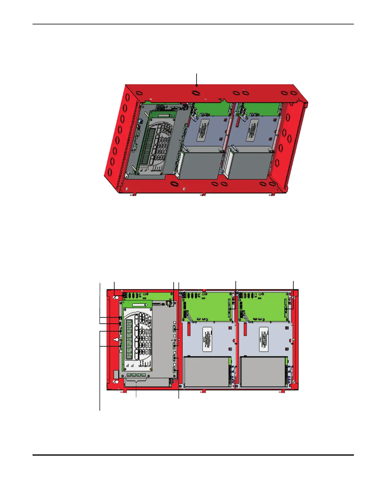
Figure E-2. Example Showing Wiring in 3-Tiered Enclosure with Additional PSU/PMU Assemblies(a); Location of knockouts (b)
PMU 2
PMU 3
R-NAC 1
R-NAC 2
NAC 1
NAC 2
Maintain 1/4-in. separation between power-limited
and non-power-limited wiring. Place non-power-
limited wiring inside a conduit.
R-NAC 1 & R-NAC 2:
Power Limited or
Non-Power-Limited
NAC 1 & NAC 2: Power Limited
AUX 1 & AUX 2: Power Limited
AUX 1 & AUX 2: Power Limited
AUX 1 & AUX 2: Power Limited
AC Mains In: Non-Power Limited
Voltage-Free Relays:
Non-Power-Limited
PMU 1
PMU 2
PMU 3
Keep AC Power wiring
from PMU to PMU dressed
snug against back of enclosure..
(a)
(b)
SLC Circuits:
Power-Limited
USB Ports:
Power-Limited
Knockout
Run wires through knockouts
as shown to keep power-limited
and non-power-limited outputs
separate.
 Loading...