EasyManua.ls Logo

UTC Fire and Security FenwalNET 8000-ML User Manual

UTC Fire and Security FenwalNET 8000-ML
242 pages
To Next Page IconTo Next Page
Page #1 background imageLoading...
Page #1 background image
P/N 06-237041-001
February 2011
R
Protection Systems
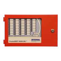
FenwalNET 8000-ML
TM
Intelligent
Fire Alarm-Suppression
Control Unit
(Installation, Operation, and
Maintenance Manual)
FM Approvals
Project ID 3038124
UL Listing File
No. S2422

Table of Contents

Questions and Answers:

UTC Fire and Security FenwalNET 8000-ML Specifications

General IconGeneral
BrandUTC Fire and Security
ModelFenwalNET 8000-ML
CategoryControl Unit
LanguageEnglish

Summary

SAFETY SUMMARY

CHAPTER 1 GENERAL INFORMATION

1-5 SYSTEM COMPONENTS

Lists the main components of the basic FenwalNET 8000-ML control unit, including enclosure, MCB, PSU/PMU, and batteries.

1-8 KEYPAD AND DISPLAY

Explains the built-in keypad and display as the primary interface for system operation, configuration, and testing.

1-9 MAIN CONTROLLER BOARD (MCB)

Describes the MCB as the system's central processing unit, controlling all operations and software within the FenwalNET 8000-ML system.

1-10 POWER SUPPLY/PMU ASSEMBLY

Details the components of the Power Supply/PMU Assembly, essential for system power and battery management.

1-11 BATTERIES

Specifies the types of batteries supported and requirements for calculating battery capacity for standby and alarm operations.

1-15 SIGNALING LINE CIRCUIT (SLC) DEVICES AND MODULES

Details the SmartOne Series of intelligent smoke and heat detectors and their associated modules supported by the system.

1-16 HIGH SENSITIVITY SMOKE DETECTORS

Lists supported high sensitivity smoke detectors like AnaLASER II and AIR-Intelligence ASD models.

1-17 SMARTONE ADDRESSABLE MODULES

Describes the four types of SmartOne addressable modules: Monitor, Relay, Control, and Remote Releasing Modules.

CHAPTER 2 INSTALLATION

2-3 OVERVIEW OF INSTALLATION STEPS

Provides a sequential overview of the installation process from shutting off AC power to performing final installation procedures.

2-4 STANDARD SYSTEM INSTALLATION PROCEDURE

Details the step-by-step procedure for installing a standard FenwalNET 8000-ML control unit, including surface and semi-flush mounting.

2-5 MAKING INTERNAL 24VDC POWER CONNECTIONS

Explains how to make internal 24Vdc power supply connections between the PMU Board, MCB, and expansion cards.

2-6 MAKING INTERNAL COMMUNICATION CONNECTIONS

Details internal communication connections between the MCB, PMU Board, and expansion card cages via RS485 and USB.

2-8 SETTING UP WIRING TO FIELD DEVICES

Covers requirements for field wiring, SLC wiring styles (Class-A, Class-B, Style 7), and electrical supervision.

2-9 SETTING UP COMMUNICATIONS

Explains how to configure RS232 and USB communication ports for connecting to PCs, laptops, or printers.

2-10 SETTING UP PERIPHERAL DEVICES AND ENCLOSURES

Details the setup of peripheral devices like RDCM and R-LAM, including their maximum supported numbers and wiring.

CHAPTER 3 CONFIGURATION AND PROGRAMMING

3-1.1 Initial Signaling-Line Circuit Configuration

Guides through the initial configuration and checking of SmartOne devices connected to the SLC, including the AutoLearn Routine.

3-1.2 Site-Specific Programming

Explains how to uniquely configure each FenwalNET 8000-ML system for specific applications using Auto-Setup, Remote Software, or Keypad/Display.

3-3.1 ISOLATE MENU FUNCTIONS

Explains how to prevent initiating signals and activation commands from being processed or issued, used for testing and maintenance.

3-3.3 SET MENU FUNCTIONS

Covers changing detector sensitivity, addressing devices, defining global parameters, and triggering configuration routines like AutoLearn and AutoSetup.

3-3.4 TEST MENU FUNCTIONS

Explains how service personnel can test initiating devices, perform alarm simulations, and initiate walk tests.

CHAPTER 4 OPERATION

4-3 USER INTERFACE KEYS AND FUNCTIONS

Details the operator keys and their functions located on the Keypad/Display, providing an overview of the user interface.

4-4 OPERATOR CONTROL KEYS

Lists and explains the functions of the Operator Control Keys, allowing operators to perform critical functions with a single button press.

4-9 SYSTEM STARTUP PROCEDURE

Provides a step-by-step guide for system startup procedures following successful installation, including preliminary steps and initial power-up.

4-10 FENWALNET 8000-ML SYSTEM OPERATION OVERVIEW

Gives general operating instructions for a stand-alone FenwalNET 8000-ML system, covering normal, trouble, alarm, and supervisory states.

CHAPTER 5 TESTING AND MAINTENANCE

5-2 SEMI-ANNUAL AND ANNUAL TESTING

Outlines essential tests to be performed during semi-annual or annual system inspections, including Lamp Test and Battery Test.

CHAPTER 6 TROUBLESHOOTING

Table 6-2. SLC Events

Details SLC-related error messages, probable causes, and corrective actions for devices connected to the Signaling Line Circuit.

APPENDIX B WIRING REQUIREMENTS FOR FENWALNET 8000-ML SIGNALING LINE CIRCUIT

APPENDIX C LIST OF AGENCY LISTED COMPATIBLE DEVICES

APPENDIX E ROUTINGS FOR POWER-LIMITED AND NON-POWER LIMITED WIRING

APPENDIX H CONVERSION INSTRUCTIONS FOR FENWALNET 2000

H-6 PROCEDURE

Details the step-by-step procedure for converting the FenwalNET 2000 enclosure to house FenwalNET 8000-ML electronics.