EasyManuals Logo

UTC Fire and Security FenwalNET 8000-ML User Manual

UTC Fire and Security FenwalNET 8000-ML
242 pages
To Next Page IconTo Next Page
To Previous Page IconTo Previous Page
Page #91 background imageLoading...
Page #91 background image
Installation
P/N 06-237041-001 2-43 February 2011
2-8.9 City Tie Wiring
Refer to the wiring diagram shown below (Figure 2-35) for City Tie Card connections.
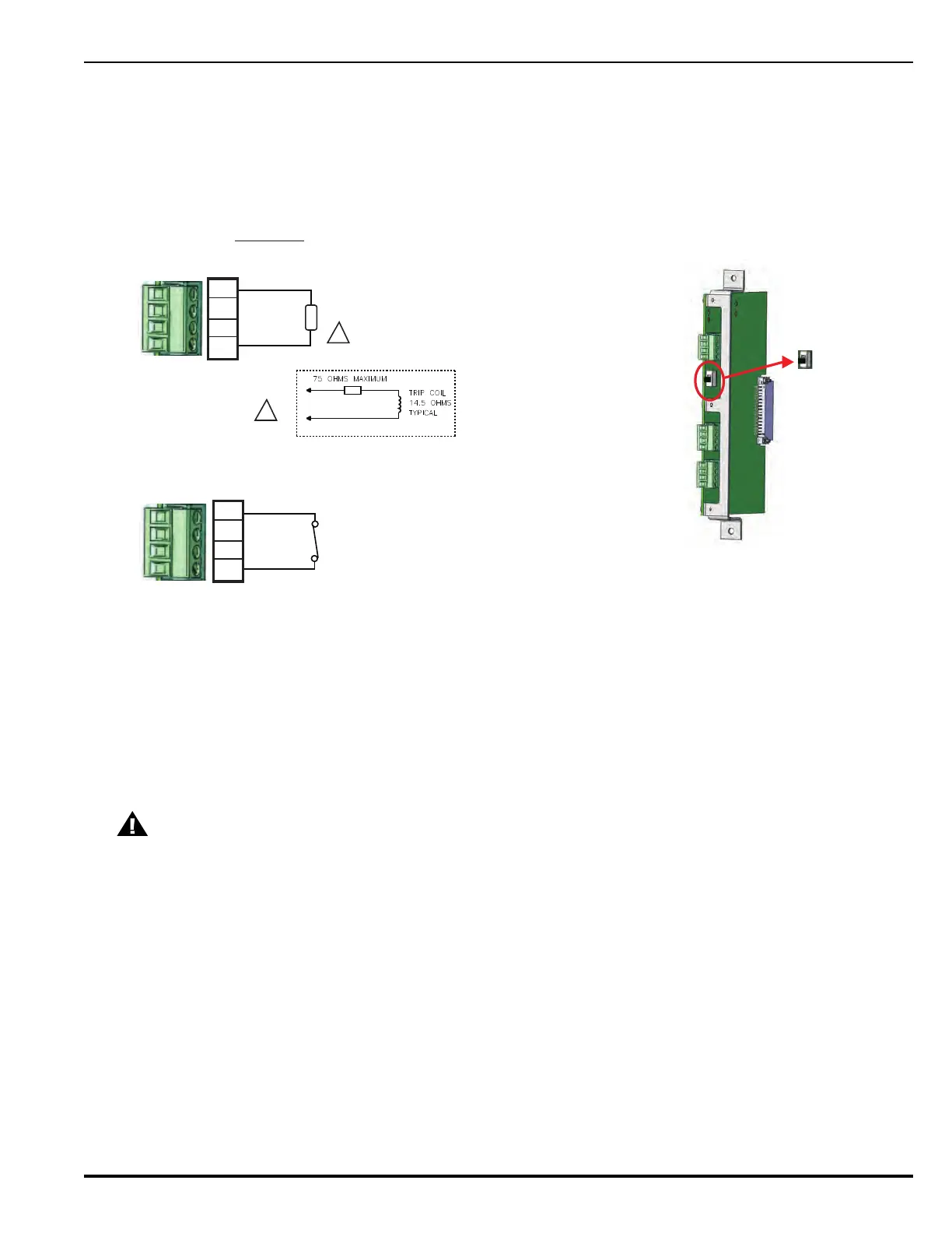
Figure 2-35. City Tie Wiring Diagram
CAUTION
Any communications wiring which exits the building or facility should not be routed to or
located inside the same conduit as the AC power.
1. Both outputs, Local Energy and Shunt, are
activated during alarm. Only one output
should be selected.
2. Reverse Polarity output is not currently implemented.
3. Maximum of one 12 AWG wire per terminal.
Installation Notes:
Shunt
OUTPUTS:
1
2
3
4
End-of-Line Resisitor 5.1K, 0.5W
(supplied with City Tie Card)
Supervised for open circuit
and ground faults.
24 Vdc; Current limited at 550 mA.
City Tie Expansion Card
Local Energy J5
Manual Disconnect Switch SW2
Reverse Polarity J7
Shunt J6
Position of Manual
Disconnect Switch:
TOP = Normal
BOTTOM = Disconnected
Not supervised
Rated at 24 Vdc @ 5.0A, resistive
The shunt connection is recognized only as a
supplementary signaling unit and is not recognized
as an auxiliary control unit connection per NFPA72.
Opens on
Alarm
Local Energy
S
1
2
3
4
End-of-Line
Resistor
S

Table of Contents

Questions and Answers:

Question and Answer IconNeed help?

Do you have a question about the UTC Fire and Security FenwalNET 8000-ML and is the answer not in the manual?

UTC Fire and Security FenwalNET 8000-ML Specifications

General IconGeneral
BrandUTC Fire and Security
ModelFenwalNET 8000-ML
CategoryControl Unit
LanguageEnglish