Installation
P/N 06-237041-001 2-19 February 2011
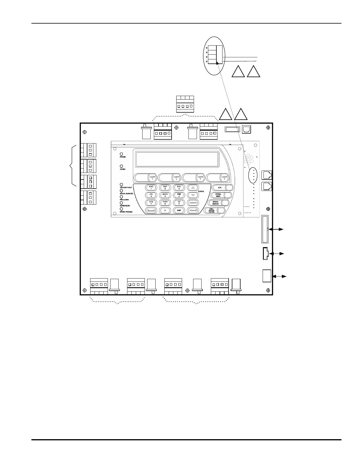
Figure 2-15. Wiring Diagram for Main Controller Board
2-4.8 Replacing Enclosure Door
When access to the internal components of the FenwalNET 8000-ML control unit is no longer
required:
1. Re-attach the enclosure door by lifting it onto its built-in hinges.
2. Attach the ground wire assembly from the Earth Ground stud located on the door to the Earth
Ground stud located on the left inside of the enclosure.
3. Close the door and lock with the provided key.
Programmable
Relays
See Figure 2-34.
Trouble Relay
TB1
RELAY 1
NO C
NC
TB2
RELAY 2
NO C
NC
TB3
RELAY 3
NO C
NC
TB
4
TBL RELAY
NO
C
NC
J20 J19
SLC 2
IN+
OUT-
IN-
OUT+
USB HOST USB DEVICE
J17
R-NAC 1
IN+
OUT-
IN-
OUT+
NORMISOL
R-NAC 2
IN+
OUT-
IN-
OUT+
J18
NAC 1
IN+ IN-
OUT+ OUT-
J16
ISOL NORM
ISOLNORM ISOLNORM
ISOL NORM
NAC 2
IN+ IN-
OUT+ OUT-
J15
ISOL NORM
RS232
A
RS232
B
J10
24 VDC IN
J2
PMU COMMS
OUT
J9
BACKPLANE
COMMS OUT
RS485
IN-B
IN-A
OUT-A
OUT-B
Main Controller Board
(
MCB
)
To PMU (J3, J4 or J5)
To Backplane (J10)
SLC 1
IN+
OUT-
IN-
OUT+
SLC 1 or 2
IN+
OUT-
IN-
OUT+
J19 or J20
S P
J8
J8
S P
To PMU (J12)
R-NAC Circuits - See
Figures 2-30, 2-32 and 2-33.
NAC Circuits - See Figure 2-30
(J15 and 16 are not able to
provide release output.)
SLC Circuits - See
Figures 2-24 and 2-25.
To RDCM or R-LAM, See Figure 2-41.
J6
J11
 Loading...