Installation
P/N 06-237041-001 2-13 February 2011
2-4.5 Installing the Audible PMU Trouble Sounder
A stand-alone buzzer, connected to the standby batteries, is located on the inside of the enclosure.
The buzzer is activated by the Trouble relay on the PMU board and sounds upon PMU
microprocessor failure and loss of AC power. The sounder is shipped attached to a small bracket
(packaged separately and provided with the control unit). The bracket assembly should be mounted
to the left side of the enclosure during installation.
Note: The Audible PMU Trouble Sounder, P/N 74-800031-004, must be installed to meet the
requirements of ANSI/UL 864.
To install the Audible PMU Trouble Sounder :
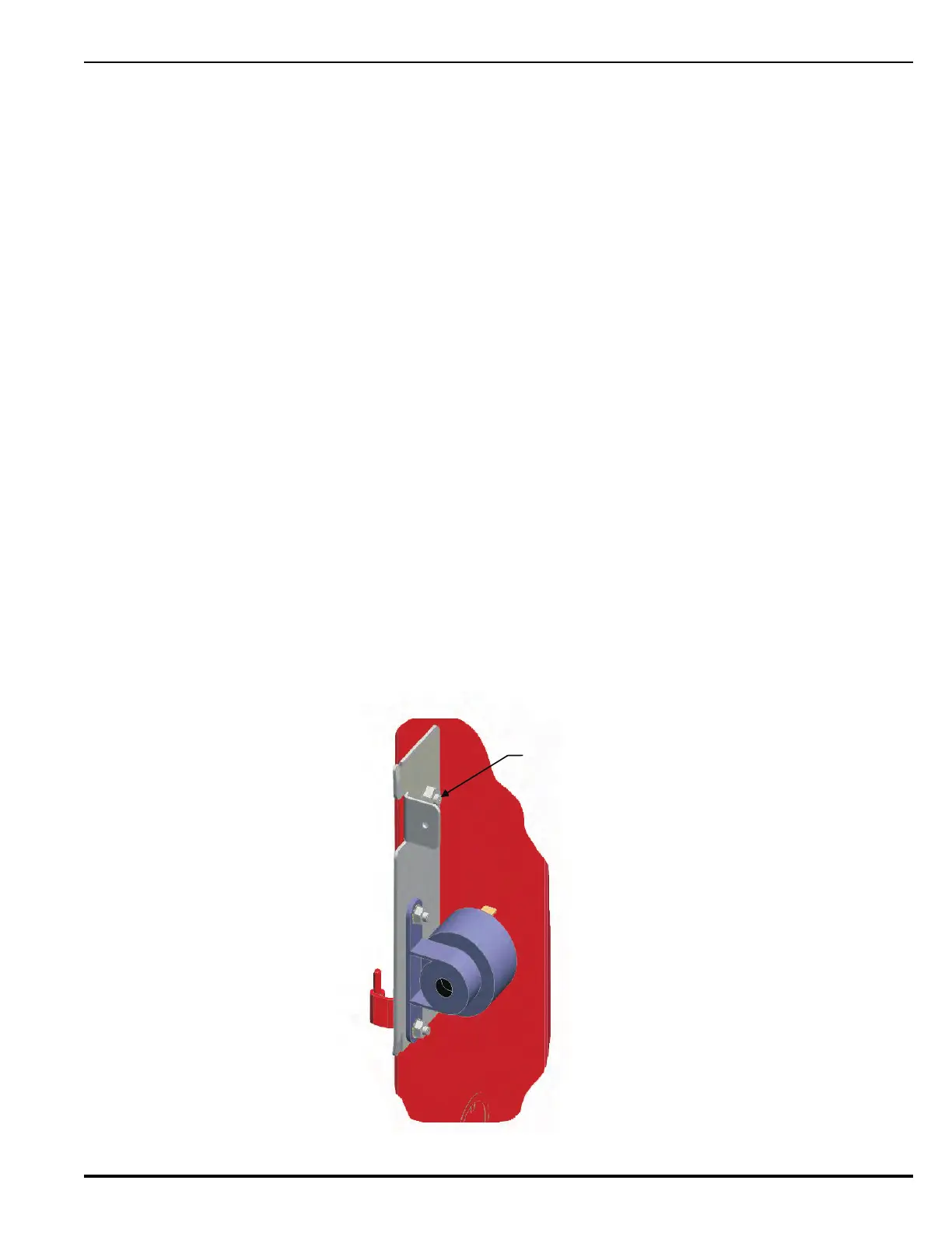
1. With the PMU Board(s) installed, unscrew the nut which is in place on the stud located on the left
side of the enclosure. Refer to the illustration below for location of the stud.
2. Place the Audible PMU Trouble Sounder bracket assembly over the stud (oriented as shown in
Figure 2-10).
3. Replace the nut and tighten to secure bracket assembly in place.
4. Next, connect wires from the Audible PMU Trouble Sounder to the PMU Board. Refer to the
wiring diagram shown in Figure 2-11.
• Connect the positive (red) wire from the sounder to the Trouble Relay Normally Open
terminal (labeled “TBL RELAY NO”).
• Connect the negative (black )wire from the sounder to the available negative Battery terminal
(labeled “Battery —”).
• Connect the power jumper (red) wire between the available positive Battery terminal (labeled
“Battery +”) and the Trouble Relay Common terminal (labeled “TBL RELAY C”).
5. Lay all wires flat against the back of the enclosure. Maintain 1/4-in. separation between power-
limited and non-power-limited wiring.
Note: A suggested method is to route the wires from the Audible PMU Trouble Sounder over the
small bracket attached to the enclosure. Refer to the wiring diagram shown in Figure 2-11.
Figure 2-10. Cutout Showing Audible PMU Trouble Sounder Mounted on Inside of Enclosure

 Loading...