Installation
P/N 06-237041-001 2-5 February 2011
2-4 STANDARD SYSTEM INSTALLATION PROCEDURE
The instructions which follow pertain to installation of a standard FenwalNET 8000-ML control unit,
which includes one Power Supply Unit, one Power Management Unit (PMU) Board and Main
Controller Board (MCB) with Keypad/Display. Installation for additional equipment follows this
section. Refer to Section 2-7.
2-4.1 Surface Mounting of Main or Expansion Enclosures
To surface mount either the 3-Tiered Enclosure (see Figure 2-1) or 2-Tiered Enclosure (see
Figure 2-4.2), do the following;
1. Mark and pre-drill holes for mounting bolts using the dimensions shown. Three keyhole slots (at
the top) and three holes (at the bottom) are located in the enclosure’s rear panel that serve as a
template for surface mounting.
Note: The installer must supply the mounting bolts (up to size 1/4-20).
2. Insert the upper three fasteners in the wall. Leave approximately 1/4” of the screws protruding.
3. Slip upper keyholes of the enclosure over the protruding screws. Tighten the screws.
4. Insert and tighten the three lower screws.
Note: It is recommended that one of the rows of mounting holes be aligned with the wall stud,
preferably the middle row of mounting holes.
5. Attach wiring conduit to the enclosure via the enclosure knockouts and pull the required number
of wires through the conduit to the enclosure. Leave approximately 2 to 3 feet of wire length in
the enclosure for field wiring connections.
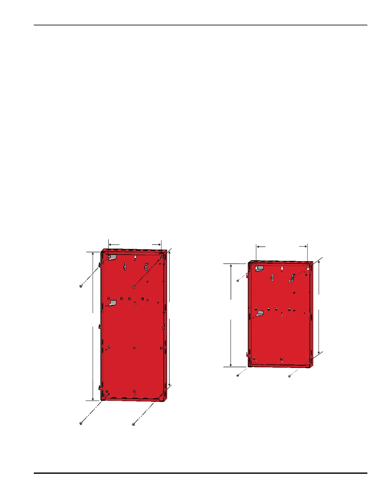
(a) (b)
Figure 2-1. Mounting Dimensions for 3-Tiered (a) and 2-Tiered (b) Main and Expansion Enclosures
31-½ in.
(800.10 mm)
12 in.
(304.80 mm)
29- in.
(746.12 mm)
⅜
12 in.
(304.80 mm)
20- in.
(517.52 mm)
⅜
22-½ in.
(571.50 mm)

 Loading...