General Information
P/N 06-237041-001 1-15 February 2011
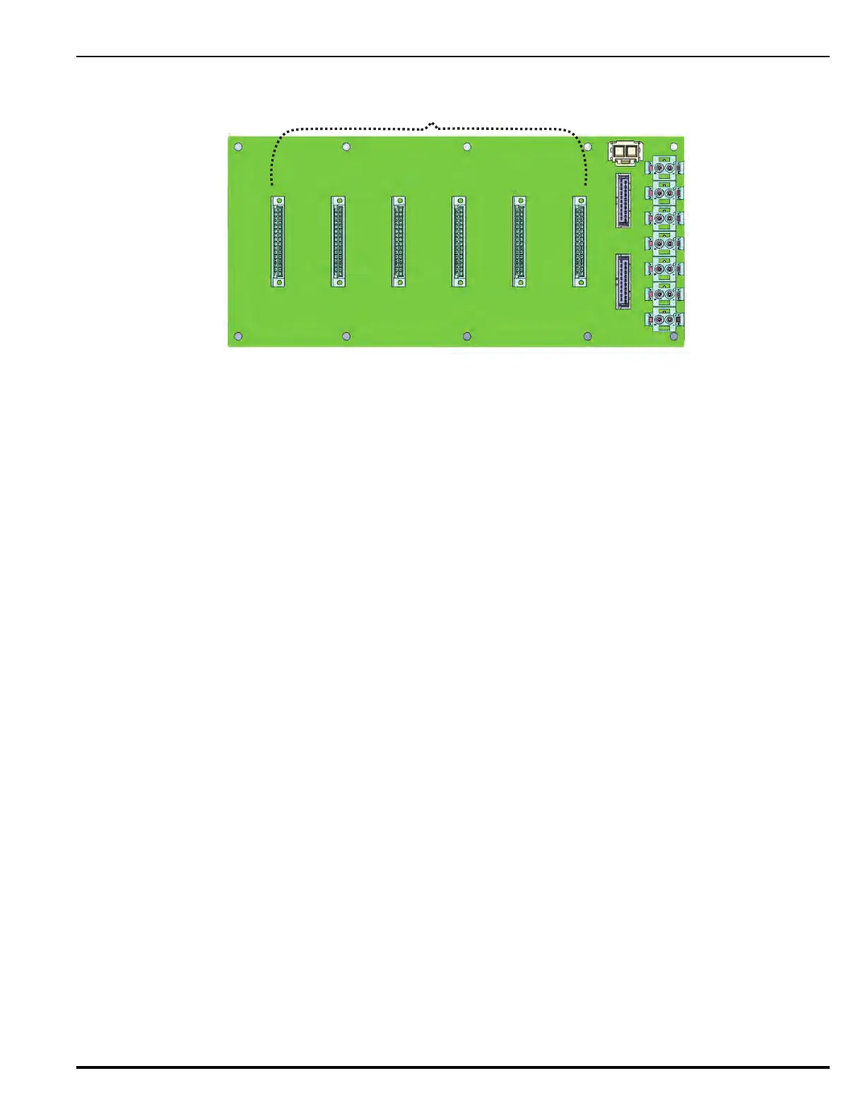
Figure 1-12. FenwalNET 8000-ML Expansion Backplane
The Expansion Backplane interfaces to the Main Controller Board and Power Supply Assembly via
two dedicated connectors: System Power IN (J9) and Communications IN (J10).
• The System Power IN connects +24 Vdc power to all six Expansion Card connectors on the
backplane.
• The Communications IN (J10) provides for the following two sets of RS485 communications
signal (originating from the Main Controller Board Communications OUT connector):
1. SLC Card
2. I/O Expansion Bus
Communications IN (J10) transfers signals to all six Expansion Card Connectors (J1-J6) on the
backplane, using a consistent set of pins/signals.
Communications OUT (J11) interfaces with the next Expansion Backplane (if applicable) to tie them
together. The Communications OUT connector uses the same set of pins/signal lines for each
backplane. These pins/signal lines also align with the Communications IN and Communications OUT
connectors on the Main Controller Board.
A backplane address, configured by position, is transferred to all six Expansion Card connectors (J1-
J6, Pins A,B,C,D), using the same set of pins/signal lines for each backplane. Each card that is
inserted into a backplane connector reads the voltage at Pins A,B,C,D and assigns an Address value.
Refer to Chapter 3 for further information on configuring addresses.
J1
J2 J3 J4
J5
J6
J9
J10
J11
Expansion Card
Backplane Connectors (6)
 Loading...