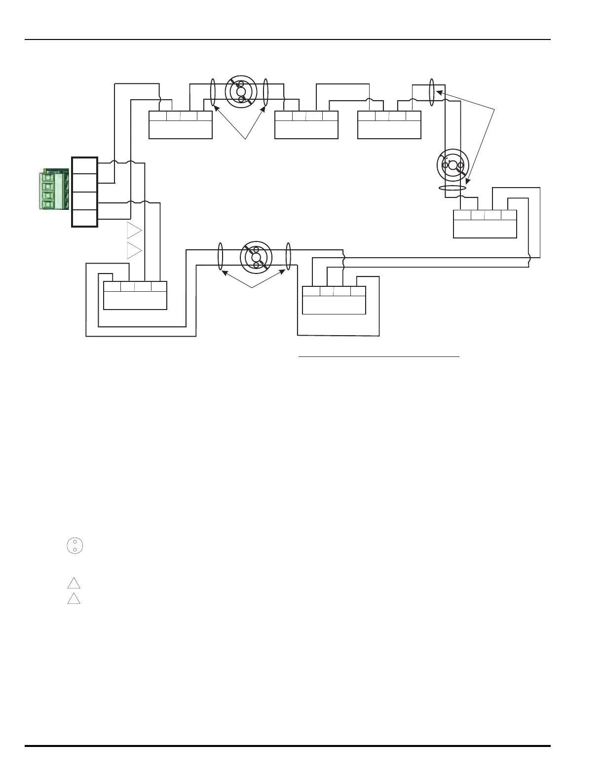
Figure 2-25. Wiring Diagram for CLASS-A, Style 7 Signaling Line Circuit
CLASS A, STYLE 7 SIGNALING LINE CIRCUIT W/LOOP ISOLATORS
3
7
ISOLATOR
LOOP
3
7
7
3
ZONE 3
ZONE 2
ZONE 1
L
S
IN -
OUT -
IN +
OUT +
RET 24V RET 24V
IN
OUT
ISOLATOR
LOOP
RET 24V RET 24V
IN
OUT
ISOLATOR
LOOP
RET 24V RET 24V
IN
OUT
ISOLATOR
LOOP
RET 24V RET 24V
IN
OUT
ISOLATOR
LOOP
RET 24V RET 24V
IN
OUT
ISOLATOR
LOOP
RET 24V RET 24V
IN
OUT
Refer to Note 10
Refer to Note 10
Refer to Note 10
SLC
Connector
INSTALLATION NOTES:
1.
SLC Devices may utilize T-tap wiring method in
CLASS B configuration only.
2.
4. Arrangements for SLC Circuit wiring:
SIGNALING LINE CIRCUIT (SLC) Specification
Maximum Voltage:
Minimum Voltage:
Maximum Line Capacitance:
Maximum Line Resistance:
Maximum Number of Devices:
Maximum Ripple Voltage:
26.4 VDC
19.0 VDC
0.5 uF
40.0 OHMS/LOOP
255
100 mV RMS
SMART DETECTORS USED:
Part Numbers 70-401001-000
70-401004-000
71-401001-000
71-401004-000
70-402001-100
71-402001-100
70-404001-100
CONTACT INPUT DEVICES:
70-407004-001
70-407003-001
70-407002-00XPart numbers
RELAY OUTPUT DEVICES:
70-408003-000
70-408002-000Part numbers
SLC TX LED - Green LED indicates normal operation of SLC
transmitter when blinking.
SLC RX LED - Yellow LED indicates normal operation of SLC
receiver when blinking.
SW1 Circuit Isolation - Isolates SLC circuit from the SLC card
containing the switch.
LOOP ISOLATORS:
Part Numbers
RXTX 74-200012-001
ELECT. BOX 74-200012-002
BASE MOUNT 74-200012-004
Maximum 20 loop isolators excluding one on SLC can be installed
on SLC circuit. No more than 30 loop devices are allowed between
two adjacent loop isolators.
3.
Maximum of 255 loop devices per SLC loop. Any
combination of device type is acceptable.
4.1
CLASS A, Style 7
CLASS A, Style 7
requires the use of loop isolators, the SLC module
requires the use of one (1) P/N 74-200012-001 isolator module
to operate in the configuration.
70-403001-XXX
70-407008-002
70-407008-001
70-408004-001
Part Number 89-100081-001
ANALASER INTERFACE MODULE
4.2
When the loop isolator is used:
Plug in the loop isolator (SLC) 74-200012-001 and interconnect
it using flex cables to J3 on SLC. Make sure that uneven pins are
interconnected.
5. Maximum of one #12 AWG wire per terminal.
6.
Loop Isolator Devices are polarized. Refer to wiring diagrams.
Denotes SmartOne Device. These
devices are not polarized.
7.
8.
For connections to SmartOne devices, refer to the wiring diagrams for
the particular device.
9.
- For power limited circuits.
- For supervised circuits.
L
S
10.
For the wiring between devices and each adjacent
isolator must be in conduit and no further than 20 feet from loop device.
CLASS A, Style 7,
 Loading...