Electrical cabling and connections vacon • 111
Local contacts: http://drives.danfoss.com/danfoss-drives/local-contacts/
6
Each fibre optic cable has a number 1...7 marked on the cable shield at both cable ends. Connect
each cable to the connectors marked with the same number 1...7 on the ASIC board and on the rear
side of the control unit.
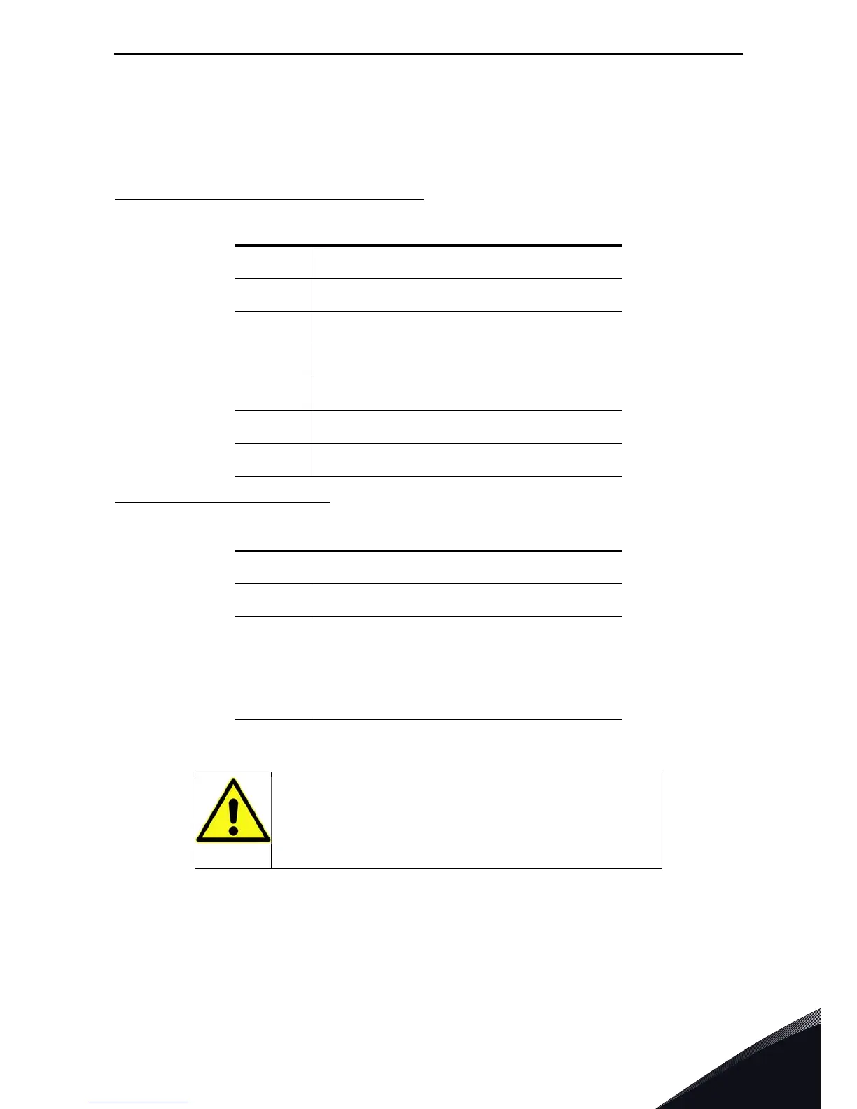
Optical terminals on Optical cable adapter board
:
Other terminals on adapter board
:
NOTE! The minimum optical cable bending radius is 50 mm.
NOTE! Terminals X2 and X3 can be in use simultaneously. However, if the +24 V supply from the
control I/O terminals (e.g. from board OPT-A1) is used, this terminal must be protected with a diode.
Fix the cable bundle at two or more points, at least one at each end, to prevent damages to the
cables.
H1 Gate control enable
H2 Phase U control
H3 Phase V control
H4 Phase W control
H5 ADC synchronization
H6 VaconBus data from control board to ASIC
H7 VaconBus data from ASIC to control board
X1 Control board connection
X2 Supply voltage 24Vin (from power unit ASIC)
X3
Supply voltage 24Vin (customer);
- Max. current 1A
- Terminal #1: +
- Terminal #2: –
CAUTION! Be careful when connecting the fibre optic cables!
Connecting the wires incorrectly
may damage power electronic components.