4
vacon • 26 Technical data
Local contacts: http://drives.danfoss.com/danfoss-drives/local-contacts/
I
th
= Thermal maximum continuous RMS current. Dimensioning can be done according to this current if the
process does not require any overloadability or the process does not include any load variation.
I
L
= Low overloadability current. Allows +10% load variation. 10% exceeding can be continuous.
I
H
= High overloadability current. Allows +50% load variation. 50% exceeding can be continuous.
All values with cosϕ = 0.83 and efficiency = 97%.
*) c = power loss into coolant; a = power loss into air; T = total power loss; power losses of input chokes not
included. All power losses obtained using max. supply voltage, I
th
and switching frequency of 3.6 kHz and
Closed Loop control mode. All power losses are worst case losses.
If some other mains voltage is used, apply the formula
P = x Un x In x cos
ϕ
x eff% to calculate the VACON
®
NX Liquid-Cooled drive output power.
The enclosure class for all VACON
®
NX Liquid-Cooled AC drives is IP00.
If the motor is continuously (besides start and stop ramps) run at frequencies below 5 Hz, pay attention to the
drive dimensioning for low frequencies, i.e. maximum I
H
= 0.66*I
th
or choose drive according to I
H
. It is
recommended to check the rating with your nearest distributor.
Drive overrating may also be necessary if the process requires high starting torque.
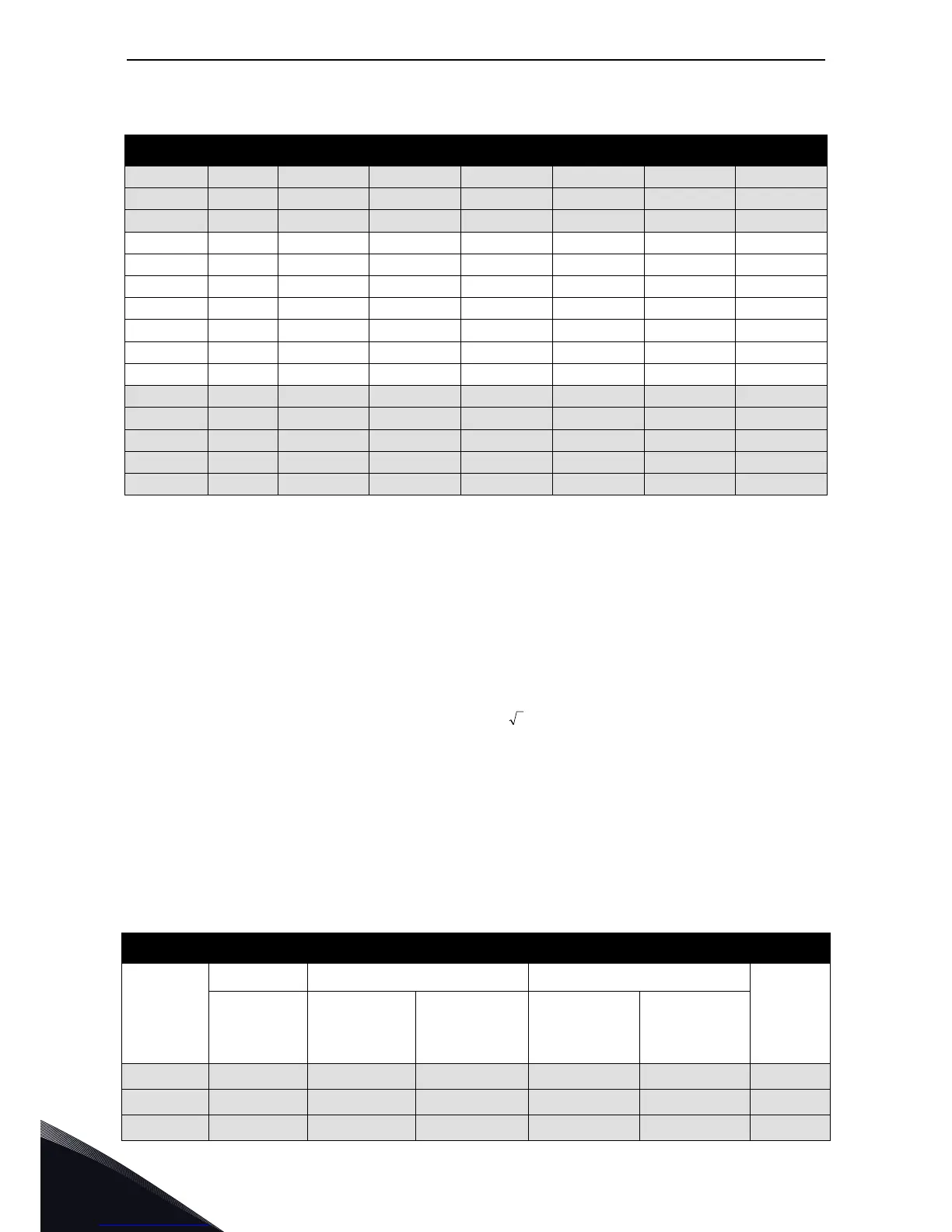
0416_6 416 378 277 250 355 9.1/0.5/9.6 CH72
0460_6 460 418 307 315 400 10.0/0.5/10.5 CH72
0502_6 502 456 335 355 450 11.2/0.6/11.8 CH72
0820_6 820 745 547 600 750 17.3/1.0/18.3 CH74
0920_6 920 836 613 650 850 19.4/1.1/20.5 CH74
1030_6 1030 936 687 750 950 21.6/1.2/22.8 CH74
1180_6 1180 1073 787 800 1100 25.0/1.3/26.3 CH74
1300_6 1300 1182 867 950 1200 27.3/1.5/28.8 CH74
1500_6 1500 1364 1000 1050 1400 32.1/1.7/33.8 CH74
1700_6 1700 1545 1133 1150 1550 36.5/1.9/38.4 Ch74
1850_6 1850 1682 1233 1250 1650 39.0/2.0/41.0 2*CH74
2120_6 2120 1927 1413 1450 1900 44.9/2.4/47.3 2*CH74
2340_6 2340 2127 1560 1600 2100 49.2/2.6/51.8 2*CH74
2700_6 2700 2455 1800 1850 2450 57.7/3.1/60.8 2*CH74
3100_6 3100 2818 2067 2150 2800 65.7/3.4/69.1 2*CH74
Table 10. Internal brake chopper unit (BCU) ratings, braking voltage 840—1100 VDC
Internal brake chopper ratings, braking voltage 840-1100 Vdc
AC drive Type
Loadability Braking capacity at 840 Vdc Braking capacity at 1100 Vdc
Chassis
Rated min
resistance
[Ω]
Rated cont. brak-
ing power
[kW]
BCU rated cont.
braking current,
I
br
[A]
Rated cont. brak-
ing power
[kW]
BCU rated cont.
braking current,
I
br
[A]
NX_325 6
1)
2.8 252 300 432 392 Ch72
NX_385 6
1)
2.8 252 300 432 392 Ch72
NX_416 6
1)
2.8 252 300 432 392 Ch72
Table 9. Power ratings of VACON
®
NX Liquid-Cooled AC drive (12-pulse),
supply voltage 525—690 VAC
Mains voltage 525-690 VAC, 50/60 Hz, 3~, 12-pulse drives