Technical data vacon • 29
Local contacts: http://drives.danfoss.com/danfoss-drives/local-contacts/
4
I
L
= Low overloadability current. Allows +10% load variation. 10% exceeding can be continuous.
I
H
= High overloadability current. Allows +50% load variation. 50% exceeding can be continuous.
All values with cosϕ = 0.83 and efficiency = 97%.
*) c = power loss into coolant; a = power loss into air; T = total power loss.
All power losses obtained using max. supply voltage, I
th
and switching frequency of 3.6 kHz and Closed Loop
control mode. All power losses are worst case losses.
If some other mains voltage is used, apply the formula DC P = (U
DC
/1.35)* *In*cos
ϕ
*eff% to calculate the
VACON
®
NX Liquid-Cooled drive electrical output power.
If the motor is continuously (besides start and stop ramps) run at frequencies below 5 Hz, pay attention to the
drive dimensioning for low frequencies, i.e. maximum I
H
= 0.66*I
th
or choose drive according to I
H
. It is
recommended to check the rating with your nearest distributor.
Drive overrating may also be necessary if the process requires high starting torque.
The voltage classes for the inverter units used in the tables above have been defined as follows:
Input 540 VDC = Rectified 400 VAC supply
Input 675 VDC = Rectified 500 VAC supply
The enclosure class of all inverter units is IP00.
4.2.2.2 VACON
®
NX Liquid-Cooled Inverter Unit – Mains voltage 640—1100 VDC
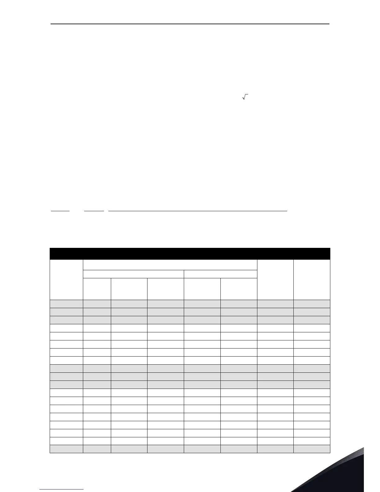
Table 12. Power ratings of VACON
®
NX Liquid-Cooled inverter unit, supply voltage 710—930 VDC
Mains voltage 640-1100 VDC
*)
Inverter
type
Drive output
Power loss
c/a/T
*)
[kW]
Chassis
Current Motor output power
Thermal
I
th
[A]
Rated cont. I
L
[A]
Rated cont. I
H
[A]
Optimum
motor at I
th
(710VDC) [kW]
Optimum
motor at I
th
(930VDC) [kW]
0170_6 170 155 113 110 160 3.6/0.2/3.8 CH61
0208_6 208 189 139 132 200 4.3/0.3/4.6 CH61
0261_6 261 237 174 160 250 5.4/0.3/5.7 CH61
0325_6 325 295 217 200 300 6.5/0.3/6.8 CH62
0385_6 385 350 257 250 355 7.5/0.4/7.9 CH62
0416_6 416 378 277 250 355 8.0/0.4/8.4 CH62
0460_6 460 418 307 300 400 8.7/0.4/9.1 CH62
0502_6 502 456 335 355 450 9.8/0.5/10.3 CH62
0590_6 590 536 393 400 560 10.9/0.6/11.5 CH63
0650_6 650 591 433 450 600 12.4/0.7/13.1 CH63
0750_6 750 682 500 500 700 14.4/0.8/15.2 CH63
0820_6 820 745 547 560 800 15.4/0.8/16.2 CH64
0920_6 920 836 613 650 850 17.2/0.9/18.1 CH64
1030_6 1030 936 687 700 1000 19.0/1.0/20.0 CH64
1180_6 1180 1073 787 800 1100 21.0/1.1/22.1 CH64
1300_6 1300 1182 867 900 1200 24.0/1.3/25.3 CH64
1500_6 1500 1364 1000 1050 1400 28.0/1.5/29.5 CH64
1700_6 1700 1545 1133 1150 1550 32.1/1.7/33.8 CH64
1850_6 1850 1682 1233 1250 1650 34.2/1.8/36.0 2*CH64