4
vacon • 30 Technical data
Local contacts: http://drives.danfoss.com/danfoss-drives/local-contacts/
*) Mains voltage 640-1200 VDC for NX_8 inverter units
I
th
= Thermal maximum continuous RMS current. Dimensioning can be done according to this current if the
process does not require any overloadability or the process does not include any load variation.
I
L
= Low overloadability current. Allows +10% load variation. 10% exceeding can be continuous.
I
H
= High overloadability current. Allows +50% load variation. 50% exceeding can be continuous.
All values with cosϕ = 0.83 and efficiency = 97%.
*) c = power loss into coolant; a = power loss into air; T = total power loss.
All power losses obtained using max. supply voltage, I
th
and switching frequency of 3.6 kHz and Closed Loop
control mode. All power losses are worst case losses.
If some other mains voltage is used, apply the formula DC P = (U
DC
/1.35)* *In*cos
ϕ
*eff% to calculate the
VACON
®
NX Liquid-Cooled drive output power.
The voltage classes for the inverter units used in the tables above have been defined as follows:
Input 710 VDC = Rectified 525 VAC supply
Input 930 VDC = Rectified 690 VAC supply
The enclosure class of all inverter units is IP00.
If the motor is continuously (besides start and stop ramps) run at frequencies below 5 Hz, pay attention to the
drive dimensioning for low frequencies, i.e. maximum I
H
= 0.66*I
th
or choose drive according to I
H
. It is
recommended to check the rating with your nearest distributor.
Drive overrating may also be necessary if the process requires high starting torque.
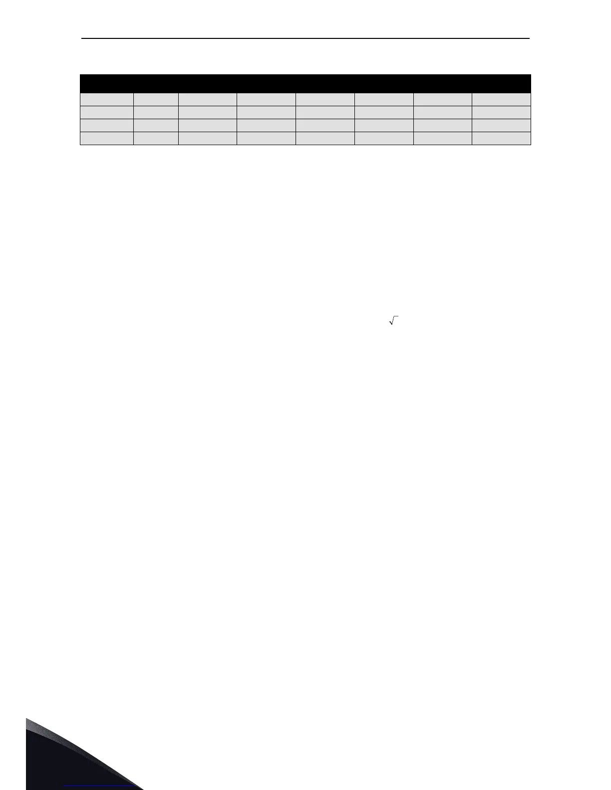
2120_6 2120 1927 1413 1450 1900 37.8/2.0/39.8 2*CH64
2340_6 2340 2127 1560 1600 2100 43.2/2.3/45.5 2*CH64
2700_6 2700 2455 1800 1850 2450 50.4/2.7/53.1 2*CH64
3100_6 3100 2818 2066 2150 2800 57.7/3.1/60.8 2*CH64
Table 12. Power ratings of VACON
®
NX Liquid-Cooled inverter unit, supply voltage 710—930 VDC
Mains voltage 640-1100 VDC
*)