Vertiv | NetSure™ 8200 Series -48 VDC Power System Installation Manual (IM582140000) | Rev. A
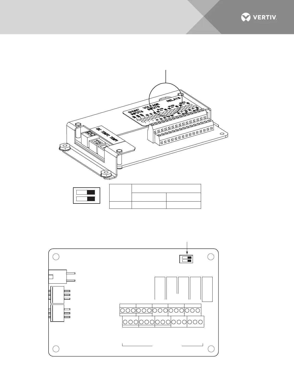
Figure 75: EIB Extended Interface Board Switch Settings
ON OFF
1
2
SW1
Setting
DIP Switch SW1
21
EIB OFF
OFF
SW1
In this system, switch settings
must be in positions shown.
EIB Circuit Card (Top View)
(Controller Extended Interface Board)
J4
SW1
J2
J3
J5 J6 J7 J8
J9
2 4 6
31 5
2 4 6
31 5
2 4 6
31 5
2 4 6
31 5
2
4 6
31 5
-
+
Shunt
Inputs
Voltage
Inputs
Voltage Inputs Relays
Sh1
V1
V2
V3 V5 V7 V8
V4 V6
RLY3
RLY1
Sh2
Sh3
Sh1 Sh2 Sh3
NOCNC NOCNC NOCNC
NOCNC NO
CNC
Relays
RLY5 RLY2 RLY4
Terminal Blocks
ON OFF
1
2
this corner of the EIB circuit card.

 Loading...


