Vertiv | NetSure™ 8200 Series -48 VDC Power System Installation Manual (IM582140000) | Rev. A
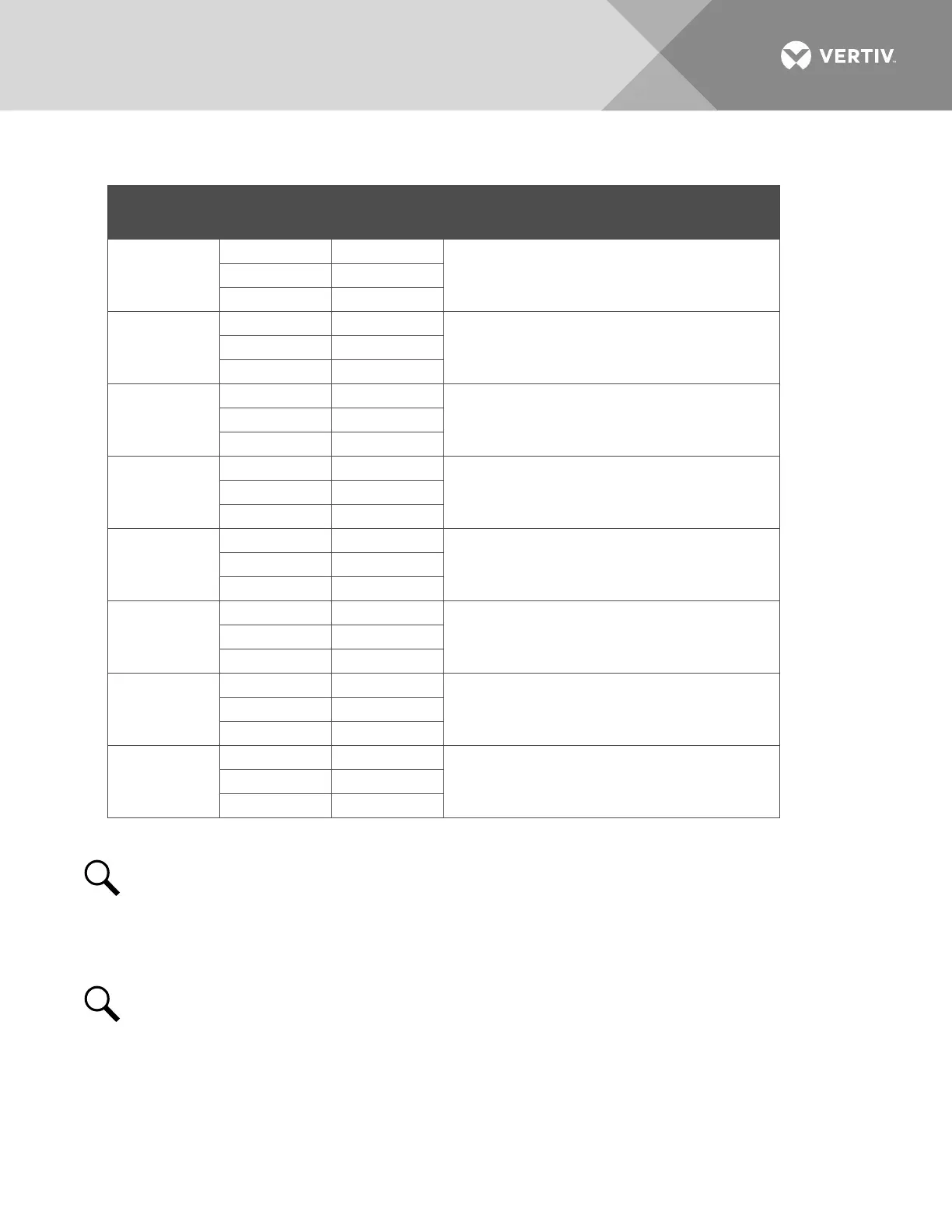
Table 6:
Relay Outputs (Factory Default) – IB2
Programmable Relay Output
IB2
Pin No.
Alarms Assigned to this Relay (Default)
IB2-1 DO1
NC J6-1
Major Summary
NO J6-5
IB2-1 DO2
Minor Summary COM J6-4
IB2-1 DO3
NC J7-1
Mains Failure
NO J7-5
IB2-1 DO4
Fuse Alarm COM J7-4
IB2-1 DO5
NC J8-1
Under Voltage 1
NO J8-5
IB2-1 DO6
Over Voltage 1 COM J8-4
IB2-1 DO7
NC J9-1
Under Voltage 2
NO J9-5
IB2-1 DO8
Over Voltage 2 COM J9-4
NOTE!
The controller relay assigned to “Major Summary” alarm (relay 1 by default) will operate in the
“Fail Safe Mode”. “Fail Safe Mode” means Relay 1 is de-energized during an alarm condition, opening the
contacts between the C and NO terminals, and closing the contacts between the C and NC terminals.
The controller’s seven (7) remaining relays energize during an alarm condition, closing the contacts
between the C and NO terminals, and opening the contacts between the C and NC terminals.
NOTE!
The relays may be preprogrammed for specific functions. Refer to the configuration drawing
(C-drawing) supplied with your system for your system’s specific configuration.

 Loading...


