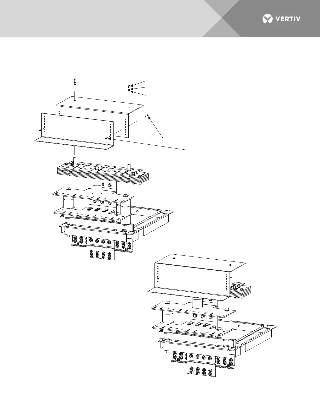
EasyManuals Logo

Vertiv NetSure 8200 Series Installation Manual

Vertiv NetSure 8200 Series
198 pages
To Next Page IconTo Next Page
To Previous Page IconTo Previous Page
Page #60 background imageLoading...
Page #60 background image
Vertiv | NetSure8200 Series -48 VDC Power System Installation Manual (IM582140000) | Rev. A
60
Figure 37:
Power/Distribution Bay External Top-Mount Ground (Load Return) Busbar Assembly (P/N 514688
or 514689) Assembly Procedure Step 4
STEP 4
Install "Covers".
(2) 1/4-20 x 1/2" Bolt, P/N 227640200
(2) 1/4" Lock Washer, P/N 215111100
(2) 1/4" Flat Washer, P/N 214110100
Torque to 45 in-lbs.
(2) 10-32 Lock Nut, P/N 104564
(2) 10-32 x 3/4" Tap Screw, P/N 218706500
DO NOT PERFORM THIS STEP if you are going to install
"Load Return Lug Extension Busbar Assembly" P/N 514543
P
/
N
5
1
4
5
2
0
P
/
N
5
1
4
5
2
1
A
s
semb
led
View
Rear
Top
of Bay

Table of Contents

Other manuals for Vertiv NetSure 8200 Series

Questions and Answers:

Question and Answer IconNeed help?

Do you have a question about the Vertiv NetSure 8200 Series and is the answer not in the manual?

Vertiv NetSure 8200 Series Specifications

General IconGeneral
BrandVertiv
ModelNetSure 8200 Series
CategoryPower Supply
LanguageEnglish

Related product manuals