Home
Vertiv
Power Supply
NetSure 8200 Series
Vertiv NetSure 8200 Series Installation Manual
4
of 1
of 1 rating
198 pages
Give review
Manual
Specs
To Next Page
To Next Page
To Previous Page
To Previous Page
Loading...
Vertiv
|
NetSure
™
8200
Ser
ies
-
48 VDC Power System
Installation
Manual (
IM5821
40000
)
|
Rev. A
61
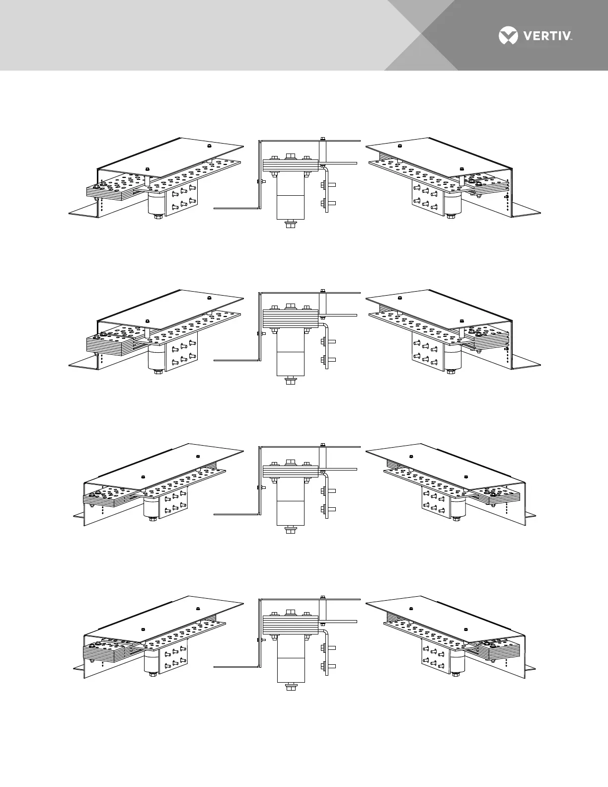
Figure
38
:
Power/Dist
ribution Bay External Top
-
Mount Ground (Load R
eturn)Busbar Assembly (
P/N 514688,
514689, 5146
90, and 514691)
Assembl
ed V
iews
Assembled Views P/N 514691
Assembled Views P/N 514690
Assembled Views P/N 514689
Assembled Views P/N 514688
60
62
Table of Contents
Default Chapter
3
Table of Contents
3
Admonishments Used in this Document
6
Important Safety Instructions
7
Safety Admonishments Definitions
7
General Safety
7
Voltages
7
AC Input Voltages
7
DC Output and Battery Voltages
7
Battery
8
Personal Protective Equipment (PPE)
9
Hazardous Voltage
9
Handling Equipment Containing Static Sensitive Components
9
Maintenance and Replacement Procedures
9
Static Warning
10
Customer Documentation Package
11
Installation Acceptance Checklist
12
Placing the Bays and Installing Internal/External Busbars
14
General Requirements
14
(Without PDSC)
14
(With PDSC)
16
Bays
17
Placing and Securing List 116, 117, 118, and 122 Distribution Only Bays
19
And Positive Busbar Links
38
Style Bay)
41
Connecting Power/Distribution Bay Rectifier Mounting Position AC Input Connectors to PDSC (Lists 102 and 112 Only)
43
Installing Power/Distribution Bay External Top-Mount Horizontal Battery Input Busbar Assembly, P/N 554873 (if Furnished)
44
528482 (if Furnished)
53
Installing Power/Distribution Bay External Top-Mount Ground
54
Furnished)
54
Installing Power/Distribution Bay Load Return Lug Extension Busbar Assembly, P/N 514543 (if Furnished)
70
Installing Power/Distribution Bay External Top-Mount Vertical Battery Input Busbar Assembly, P/N 554874 (if Furnished)
79
Installing Distribution Only Bay External Top-Mount Ground (Load Return) Busbar Assembly; P/N 528775 (if Furnished)
88
Installing Distribution Only Bay External Top-Mount Ground (Load Return) Extension Busbar Assembly; P/N 528780 (if Furnished)
90
Installing Distribution Fuses and Circuit Breakers
93
Installing 218 Circuit Breakers, TPL Fuseholders, and Bullet Nose-Type Device Mounting Assemblies into Power/Distribution Bays
93
Only Bays
93
Installing TPL Fuses
94
Installing TLS/TPS Fuses
94
Installing Bullet Nose-Type Circuit Breakers
94
Installing an Optional Bullet Nose-Type 10-Position GMT Fuse
95
Module
95
Storing Spare Fuses
95
Recording Fuse and Circuit Breaker Sizes
95
Making Switch and Jumper Settings
110
Switch Settings on IB2 and EIB Interface Boards
110
Switch Settings on SM-DUE
114
Jumper Settings on SM-DUE
115
Jumper Setting on Distribution Bus Monitoring Circuit Cards
117
Use in Systems with an MCA Only)
117
Making Electrical Connections
119
Important Safety Instructions
119
Wiring Considerations
119
Bay-To-Bay Interconnections
119
Distribution Only Bay BAT RTN Connection to System Monitoring
123
And Control Section
123
External Alarm, Reference, and Control Connections
124
Connector Locations on Inside of Primary Power/Distribution Bay and Primary Power Only Bay Front Door
124
Connector Locations on Primary Power/Distribution Bay and Primary
125
Power Only Bay Control Shelf
125
Connector Locations on Secondary Power/Distribution Bay and Secondary Power Only Bay Control Shelf
126
Local Area Network (LAN) Ethernet Port Connection (IB4 Board)
127
IB2 (Controller Interface Board) Connections (if Required)
129
EIB (Controller Extended Interface Board) Connections (if Required)
135
Customer Connections to SM-DUE (if Required)
142
Surge Suppression Alarms (if Option Installed)
150
Bay Frame Grounding Connections
151
Load Connections
153
AC Input and AC Input Ground Connections
162
Battery Connections
175
Re-Install Shields and Cover Panels
180
Installing the Rectifiers
181
Initially Starting, Configuring, and Checking System Operation
182
Initial Startup Preparation
182
Initially Starting the System
182
NCU Controller Initialization
182
Verifying and Setting the NCU Controller as Required for Your
185
Application
185
General
185
Using the NCU Local Display and Keypad
185
Using the NCU Start Wizard from the NCU Local Display and Keypad
186
Using the Primary Power/Distribution Bay or Primary Power Only Bay Front Panel Touch Screen to Access the NCU Webpages
186
Verifying the Configuration File
186
Checking Basic System Settings
187
Changing Battery Capacity Rating in the NCU
189
Configuring the NCU Identification of Rectifiers and Assigning Which Input Feed Is Connected to the Rectifiers
189
NCU Alarm Relay Check
190
Checking AC Fail Alarm
190
Checking Rectifier Alarm
190
Checking System over Voltage Alarm 1 and over Voltage Alarm 2
191
Checking System under Voltage Alarm 1 and under Voltage Alarm 2
193
Checking Circuit Breaker/Fuse Alarm
194
Checking System Status
196
Final Steps
197
Other manuals for Vertiv NetSure 8200 Series
User Manual
56 pages
Installation And User Manual
22 pages
4
Based on 1 rating
Ask a question
Give review
Questions and Answers:
Need help?
Do you have a question about the Vertiv NetSure 8200 Series and is the answer not in the manual?
Ask a question
Vertiv NetSure 8200 Series Specifications
General
Brand
Vertiv
Model
NetSure 8200 Series
Category
Power Supply
Language
English
Related product manuals
Vertiv NetSure 801 AG1
76 pages
Vertiv NetSure 731 A91
40 pages
Vertiv NetSure 531 A91
40 pages
Vertiv NetSure V200E50
36 pages
Vertiv NetSure R48-3000e3
22 pages
Vertiv NetSure 5100 Series
80 pages
Vertiv NetSure 7100 Series
130 pages
Vertiv NetSure 2100 Series
24 pages
Vertiv ALPHA 1800
4 pages
Vertiv Liebert APM 400
97 pages

 Loading...


