Vertiv | SmartCabinet | User Manual 55
System Commissioning
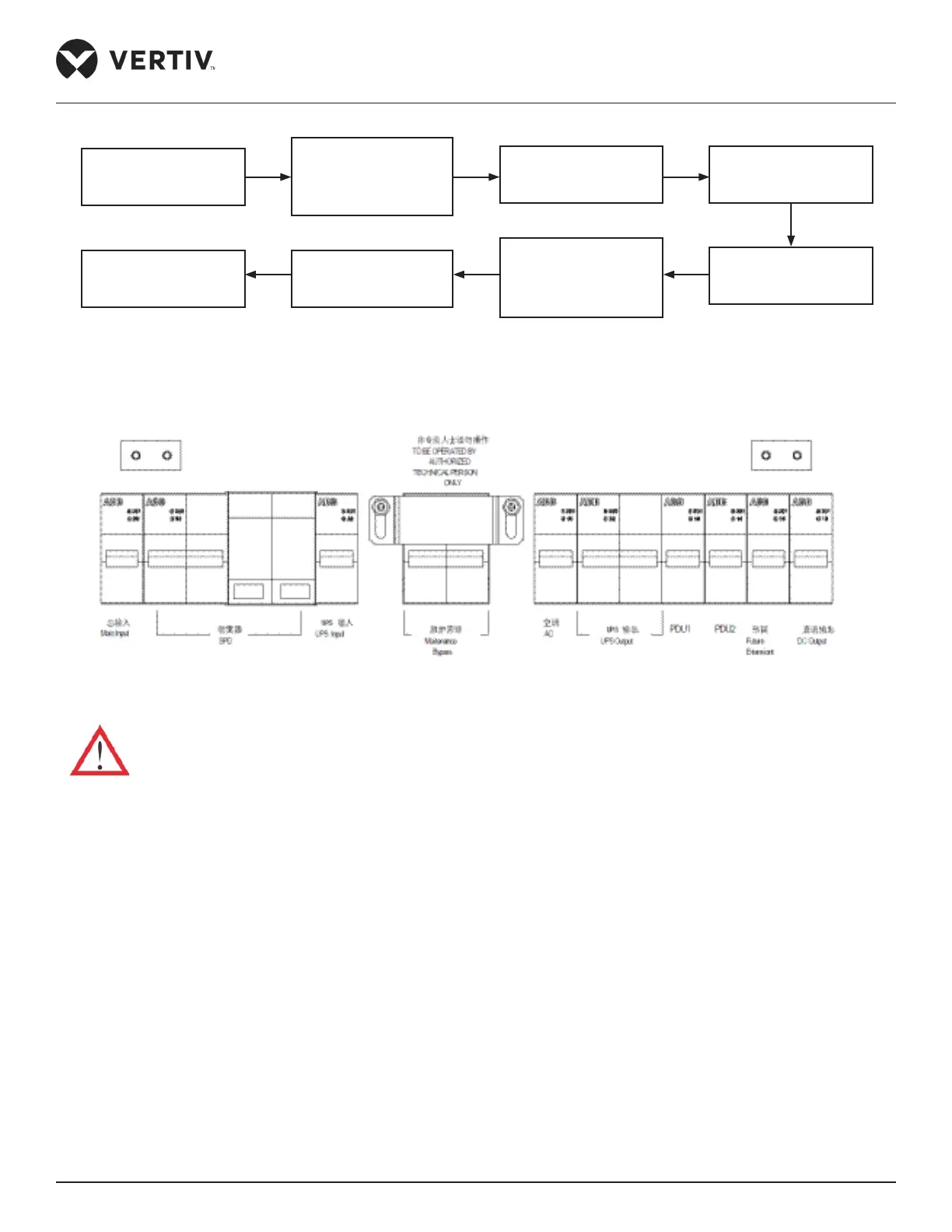
Figure 3-2 Startup owchart
The following diagram shows the layout of the MCBs:
Figure 3-3 Layout of the MCBs
• Before starting up the UPS, disconnect the UPS output MCB and the bypass.
Following are the set of procedures to be implemented in the Startup process (in the following hierarchy):
1. Close the external input power switch.
2. Close the UPS rear part input MCB.
3. Close the UPS input MCB and UPS output MCB one by one.
4. The UPS LCD displays the self test screen, and the fault indicator (red) and inverter indicator (green) are
both on for about 5s. After self test, the UPS enters the bypass mode and the fault indicator turns on, and
the buzzer beeps for 1s.
5. The rectier startup is completed 30s after the rectier enters the normal operation status, and then
complete verifying the single unit parameter settings.
Closing external input
power switch
Closing the air-
breakers of total input
of PMU, SPD, UPS
input, USP output
Wait for UPS checking-
self and startup
UPS Startup
Closing the AC Switch
and wait for the AC
startup
Closing the air-
breakers of PDU,
lighting and LCD,
intelligent lock in turn
Wait for LCD and
monitoring systme
startup
Startup user devices