Vertiv | SmartCabinet | User Manual 44
System Installation
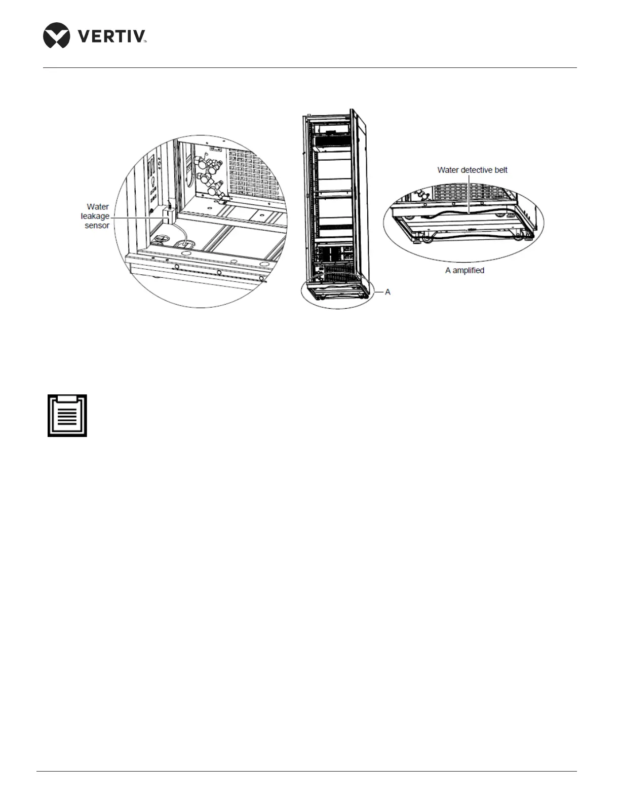
Figure 2-34 shows an illustration of the installation of the water leakage sensor:
Figure 2-34 Installing the water leakage sensor
2.3.8. Cable Connections
• All the external input cables are user-prepared meaning the customer is solely responsible for obtain-
ing and preparing the external input cables.
• The power cables which are used must be in compliance to the local electrical standards for cables.
• Bind the power cables and communication cables separately on the cable organizers on both sides in
the rear space of the cabinet. Vertiv recommends that the power cables should be managed on the
right cable organizer while the communication cables should be managed on the left cable organizer.
The wiring of the PMU, UPS, PDU, intelligent emergency fan, and AC power inside the cabinet is already
congured and completed prior to delivery. All that needs to be done is to connect the cable between the
UPS and the battery, and the UPS input and output cables (lines have been reserved on the ports).