Vertiv | SmartCabinet | User Manual 64
System Operation
The menu structure of the Operation & Display panel is displayed in Figure 4-2.
Figure 4-2 Description on Cabinet Power Connection
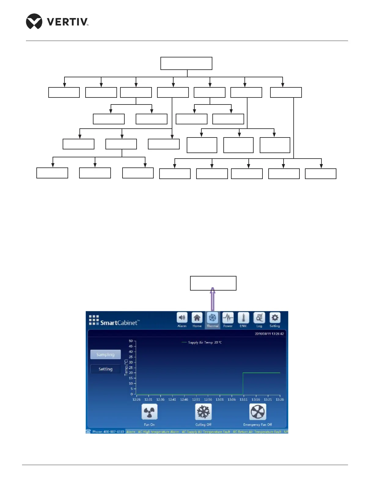
4.1.1. Thermal Management
screen (Refer Figure 4-3):
Figure 4-3 Thermal Management
LCD
Alarm Thermal Power ENV. Log Setting
SettingSampling SettingSampling
PDU1UPS PDU2
ControlSampling Setting
Language Password Network System
Alarm
Active
Alarm
Control
Alarm
Thermal Icon