Vertiv | SmartCabinet | User Manual 49
System Installation
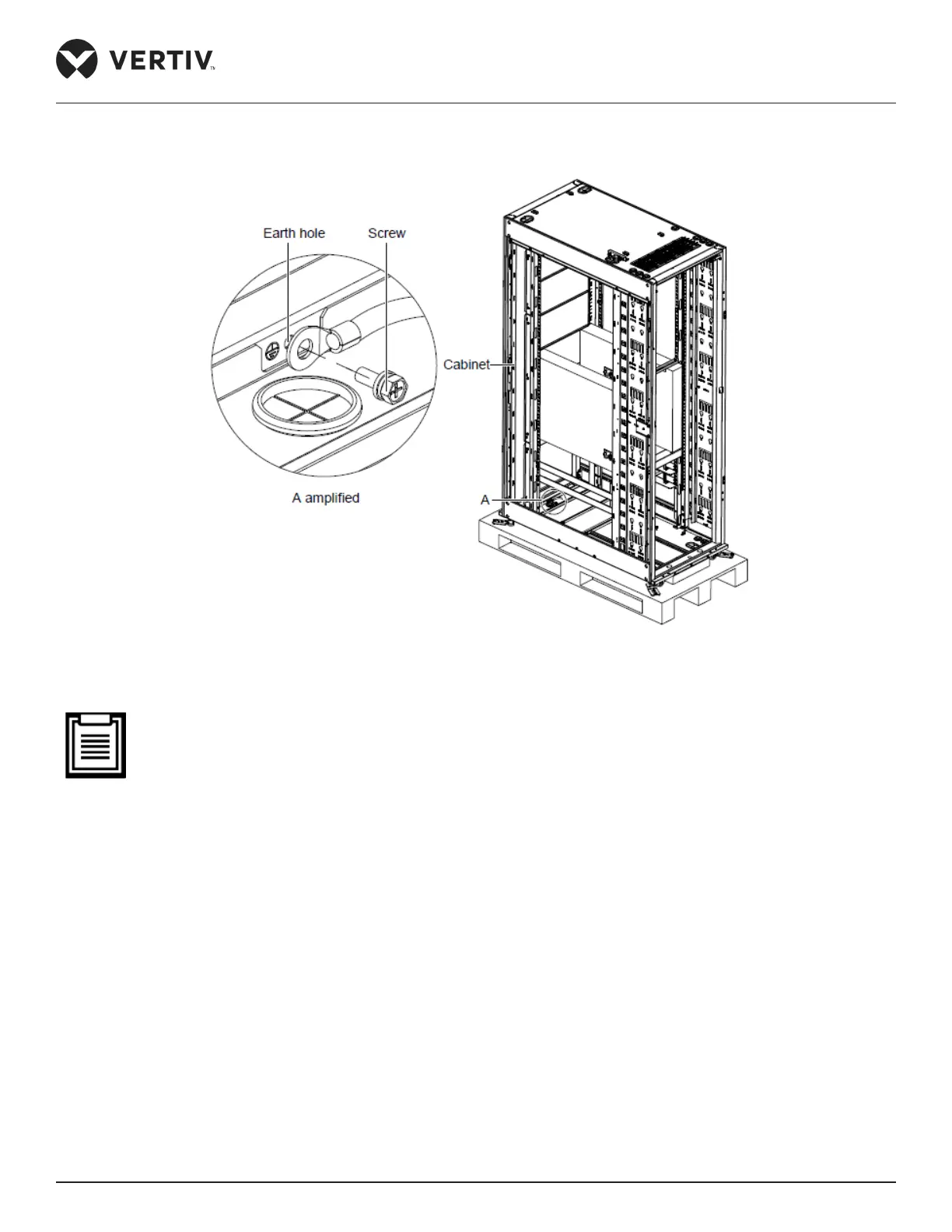
Figure 2-39 shows the illustration of the earth cable connection:
Figure 2-39 Connecting the earth cable
• This product is only applicable to the TN system. To ensure safety, the cabinet and AC components
should be grounded properly.
• Use a yellow green earth cable of no less than 6 mm² and connect it to the earth copper bar of the com-
puter room accurately.
• While xing the M6 screw on the earth hole of the cabinet, Vertiv recommends the use of a wrench.
• If an earth block doesn’t exist in the building where the SmartCabinet is placed, use a yellow-green cable
of no less than 6 mm² to connect the earth terminal of the cabinet with that of the PMU total input; this
ensures reliable earthing of the cabinet.
2.3.9. Conguration of the Communication Address and Port
Set the addresses of the 4DIF sensor through the DIP switch, as shown in Figure 2-40 and in Table 2-14: